Utilization of Spinal Navigation to Facilitate Hassle-Free Rod Placement during Minimally-Invasive Long-Construct Posterior Instrumentation
Article information
Abstract
During minimally-invasive long-construct posterior instrumentation, it may be challenging to contour and place the rod as the screw heads are not visualized. To overcome this, we utilized the image data merging (IDM) facility of our spinal navigation system to visualize a coherent whole image of the construct throughout the procedure. Here, we describe this technique that was used for a patient in whom L1–L5 posterior instrumentation was performed. Using an IDM facility, screws are color coded and after placement, the final image is saved. Saved images of all previous screws are displayed and observed while placing the subsequent screws. Therefore, the entry point, depth, and mediolateral alignment of subsequent screws can be adjusted to fall in line with previous screws such that the rod can be placed without hassle. Moreover, final adjustments to the construct are kept to a minimum. The possibility of screw pullout due to force engaging the rod on poorly aligned screws is thus avoided.
Introduction
During posterior instrumentation via open approach, contouring and placement of the rod is relatively straightforward as the screw heads can be seen throughout the procedure. Therefore, the surgeon is always mindful about screw head position such that they are lined up to accommodate final rod placement [1-3]. However, during minimally-invasive long-construct procedures, this is not possible as the screw heads are hidden from the surgeon’s view. Thus, the surgeon may take longer to measure the appropriate rod length, require multiple fluoroscopic images, and also risks the possibility of screw pullout if the screws are not aligned properly and the rod is force engaged [4]. With the advances in spinal navigation for minimally-invasive spine surgery, we have managed to overcome this problem by a technique of image data merging (IDM) that will allow smooth insertion of the rod during navigated minimally-invasive posterior instrumentation. The technique and its surgical pearls are described below.
Technical Note
In this case, a minimally-invasive posterior instrumented fusion was performed from L1–L5. Firstly, the patient was made to lay in prone position on a Jackson table. A stab incision was made over the spinous process of T12, followed by, clamping of reference frame to the spinous process. Then, the O-arm (Medtronic StealthStation S8 surgical navigation system; Medtronic Inc., Minneapolis, MN, USA) was brought in for a reference spin. Subsequently, a midline incision was made through the skin, whereas stab incisions were made through the fascia for the pedicle screws. A navigated awl and tap were used to prepare the pedicle for the L1 screw on one side, and then the screw was inserted (Fig. 1). This technique of navigated pedicle screw insertion is similar to other techniques described in the literature [5].
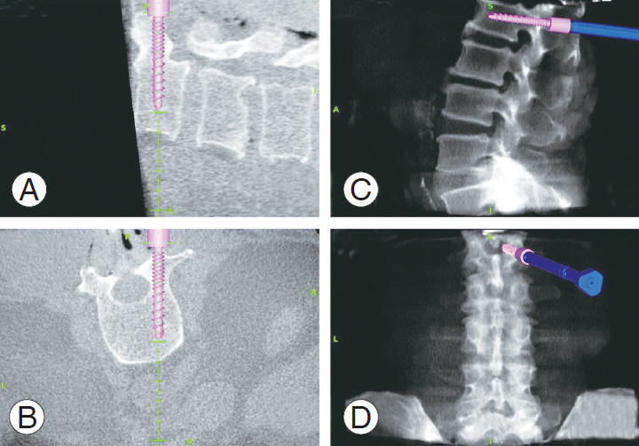
Navigation display monitor screenshot showing the placement of the right L2 pedicle screw, (A) sagittal cut at the level of right L2 pedicle, (B) axial cut at the level of L2 pedicles, (C) reference lateral view X-ray image, and (D) reference anteroposterior view X-ray image.
Planning for a hassle-free rod placement begins with the first inserted pedicle screw. We utilized the IDM facility of our navigation system to save a color coded virtual image of the first inserted L1 screw along with its screw head (Fig. 1). This serves as the reference for subsequent screws. Next, the L2 screw was inserted on the same side, considering the mediolateral trajectory and depth to keep this screw head in line with the previous screw (Fig. 2). Color coded virtual images of all previously placed screws were projected in the navigation display monitor while placing the subsequent screws, i.e., when the L4 screw was inserted, images of the L2 and L3 screws were displayed. The L4 screw was adjusted accordingly such that it lined up with the other screws to achieve the desired lordosis. The same procedure was repeated until all screws were inserted.
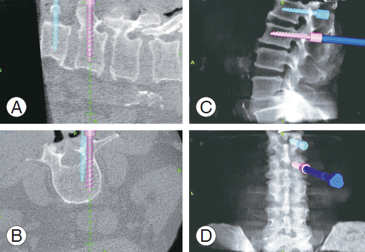
Placement of right L3 pedicle screw with color coded projection of previously placed L2 screw, (A) sagittal cut at the level of right L3 pedicle, (B) axial cut at the level of L3 pedicles, (C) reference lateral view X-ray image, and (D) reference anteroposterior view X-ray image.
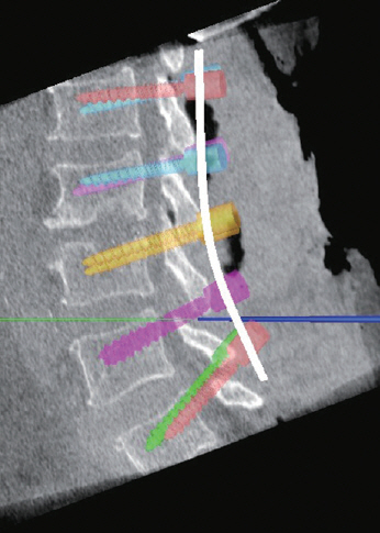
Once all screws from L1 to L5 were in place, virtual images of the screws were merged and displayed to plan the contour of the rod (Fig. 3). The same can be done separately for each side. From this merged projection, we were able to perform the following tasks: (1) check the depth of the screw heads, (2) check whether the screw heads line up in the mediolateral plane, (3) estimate lordosis to contour the rod, and (4) measure the length (in mm) of the rod. After contouring (Fig. 4), the rod placement was performed in a regular fashion by tunneling through the facia and secured accordingly. Postoperative X-rays were taken to check the placement of the rod.
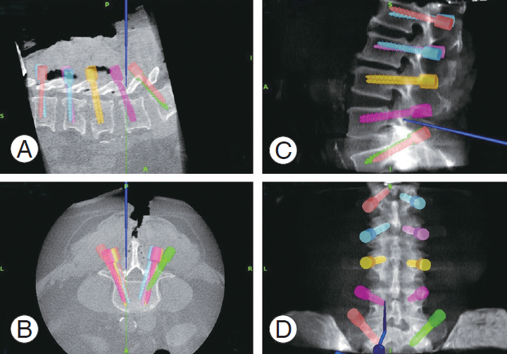
Final navigation display monitor screenshot showing the merged projection of all placed pedicle screws in different colors, (A) sagittal cut image, (B) axial cut image, (C and D) reference lateral and anteroposterior view X-ray images.
Discussion
Navigation-assisted minimally-invasive posterior instrumentation of the spine is gaining popularity owing to its multiple advantages and the field is constantly evolving [6-11]. However, there are concerns regarding appropriate rod contouring and placement as the screw heads are not visualized, particularly during long-construct posterior instrumentation [12]. If the screw heads are not properly aligned to facilitate the curvature of the rod, it may be arduous to position the rod. Moreover, it can be time consuming to remove the rod, adjust the screws, change the contour, and re-insert the rod [12]. This may require additional fluoroscopy images, leading to prolonged surgery and increased surgeon fatigue. Moreover, the rod cannot be forced in to engage with the screw heads as this will increase the risk of screw pull out [13-15].
To overcome these difficulties, we used the IDM facility of the navigation system to display all saved virtual images of screw placements to be projected every time a new screw is placed. This helps in planning the entry point, depth, and mediolateral alignment of each screw with respect to the other screws. The final merged projection of all saved virtual screw images allows the surgeon to tweak the screw position or contour the rod to facilitate hassle-free rod placement. However, these final adjustments are restricted to a minimum with the help of this IDM facility. This technique may not be limited to long-construct minimally-invasive posterior instrumentation, but can also be used during pelvic fixations, and spondylolisthesis to estimate the desired amount of correction required.
In conclusion, utilizing IDM facility of spinal navigation can help in overcoming difficulties in rod placement during minimally-invasive long-construct posterior instrumentation. This technique is vital for determining the appropriate alignment of each pedicle screw with respect to the other screws to achieve hassle-free rod placement, thereby reducing surgical time, radiation exposure, and surgeon fatigue.
Notes
No potential conflict of interest relevant to this article was reported.