Biomechanical Testing of Spinal Segment Fixed by Arcofix System on the Swine Spine
Article information
Abstract
Study Design
An in vitro biomechanical study.
Purpose
To evaluate the mechanical properties of the spinal segment in the intact, injured, and stabilized state after fixation by an Arcofix implant.
Overview of Literature
Several types of thoracolumbar spine injury necessitates anterior instrumentation. The Arcofix plate represents the latest generation of angular stablity systems. The biomechanical properties of these implants have not been sufficiently studied yet.
Methods
A total of ten porcine specimens (levels Th12-L3) were prepared. The tests were performed for intact, injured, and implanted specimens. In each state, the specimen was subjected to a tension load of a prescribed force, and subsequently, twisted by a given angle. The force load was 200 N. The torsion load had a deformation character, i.e., the control variable was the twisting angle and the measured variable was the moment of a couple. The amplitude of the load alternating cycle was 3°. Another parameter that was evaluated was the area of the hysteresis loop. The area corresponds to the deformation energy which is dissipated during the cycle.
Results
A statistically significant difference was found between the intact and injured states as well as between the injured and implanted specimens. The statistical evaluation also showed a statistically different value of the hysteresis loop area. In the case of instability, the area decreased to 33% of the physiological value. For the implanted sample, the area increased to 170% of the physiological value.
Conclusions
The Arcofix implant with its parameters appears to be suitable and sufficiently stable for the treatment of the anterior column of the spine.
Introduction
The thoracolumbar junction is the most common area of injury to the axial skeleton. Forces along the long stiff kyphotic thoracic spine switch abruptly into the mobile losrdotic lumbar spine at the thoracolumbar junction. The anterior approach is recommended for reconstruction of the anterior spinal column, particularly in burst fractures of the thoracolumbar junction [123456]. Arcofix (Synthes Inc., West Chester, PA, USA) represents the latest generation of angular stable plates for anterior spinal column stabilization. In contrast to previous implants, the Acrofix enables a reposition manoeuvre and could be used for isolated anterior reconstruction without antecedent posterior fixation. In some injuries, including those with kyphotic deformities, the one-step ventral stabilization is sufficient. The aim of our in vitro study was to evaluate whether the stability of the spinal segment implanted with Arcofix is comparable to an intact segment. We compared the mechanical properties of the sample in the intact state, destabilized (injured) state, and the state after stabilization by the Arcofix implant.
Materials and Methods
Test specimens were taken from domestic pigs. A total of ten specimens were prepared for the purposes of the experiment. We used segment levels Th12-L3. For the purposes of the mechanical tests, spinal segment had to be modified so that it could be tightened into the jaws of the testing machine. As the specimens are of organic origin, it was not possible to use fixtures designed for tests of technical materials. Both ends of the specimen were embedded in duracryl blocks that were tightened through plates with clamping pins into the jaws of a standard testing machine using six-jaw lathe chucks. The specimen tightened into the jaws of a testing machine is demonstrated in Fig. 1.
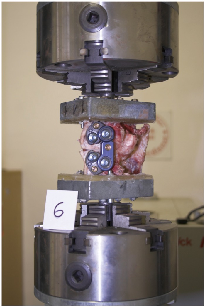
The specimen tightened in jaws of a testing machine.
The Zwick (Zwick GmbH & Co., Ulm, Gernany) testing machine with basic equipment made it possible to subject specimens to tension or torsion load, or a combination of both. The tension load selected for this experiment is rather unusual, as it almost never occurs during normal movements of a human body. However, the tension load is suitable for the purpose of the experiment, as it exposes the specimen to mechanical states that can be considered as more adverse as compared with pressure load.
The tests were performed for intact (physiological state) (Fig. 2A), injured (state of instability) (Fig. 2B), and implanted (stabilization by the implant) (Fig. 2C) specimens. Instability of the segment was created by a scalpel. We completely cut the intervertebral disc, including the ventral and dorsal longitudinal ligaments. The Arcofix plate was implanted according to the technique guide. After the cortical bone was perforated by an awl through drill sleeves, screws were inserted and locked with a torque-limiting T-handle (7 Nm; Synthes Inc.). In each state, the specimen was subjected to tension loads of a prescribed force, and subsequently, twisted by a given angle. Load values were defined based on experience with measurements of a similar nature. According to previous experiments [45], we determined the maximum safety force load to be 200 N. A higher load could lead to the specimen loosening from the duracryl block. The torsion load had a deformation character, i.e., the control variable was the twisting angle and the measured variable was the moment of a couple. The amplitude of the load alternating cycle was 3°. The value of amplitude was established based on the initial tests with regard to a maximum allowed torque of 20 Nm (as limited by the sensor).
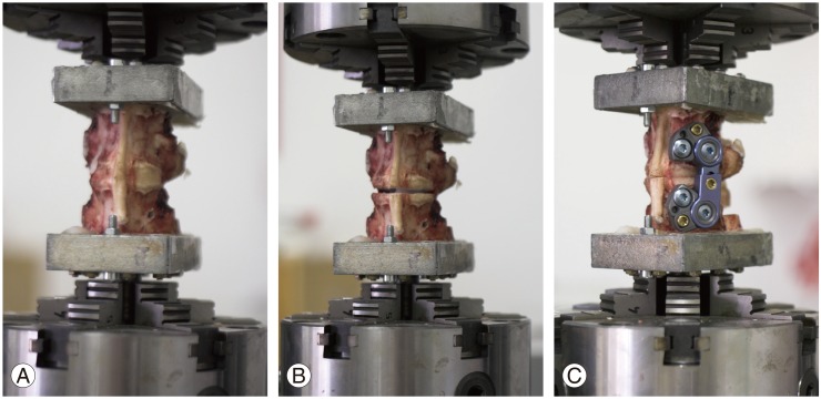
(A) Intact specimen. (B) Injured specimen. (C) Fixed specimen.
Results
1. Moment to twist the specimens
During measurements, values of a couple necessary to twist the specimens were evaluated. An example of the behaviour of force moment's dependence on the twisting angle for specimen 4 is demonstrated in Fig. 3A. Dependences of moment on time are illustrated in Fig. 3B. The maximum couple values to ensure +3° and -3° torsion are summarized in Table 1. The behaviour of the specimens under rotation (both sides) can be seen in Fig. 4, which shows the mean value and standard deviation of torque needed for twisting the specimens +3° and -3°.

Dependence of couple moment on (A) twisting angle and (B) time for specimen 4.
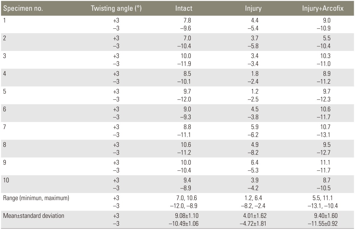
Values of moment (Nm) necessary to twist the specimens by ±3°
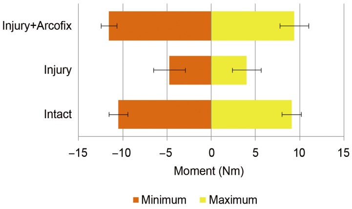
Values of the moments for right and left rotation (mean±standard deviation).
The measured maximum moments divided into three classes according to the specimen state are summarized in Fig. 5A. It was necessary to determine whether the differences between classes are statistically significant or, in other words, whether the impairment of specimens and the application of fixators affect the intensity of the moment necessary to twist the specimens. The paired t-test was used to evaluate the differences. The calculated p-values are summarized in Table 2. The test of normality at the significance level of 5% rejected the hypothesis that the data come from a normal distribution. The equality of the standard deviations and variances between each set of two populations was determined using Bartlett's test (p=0.264).
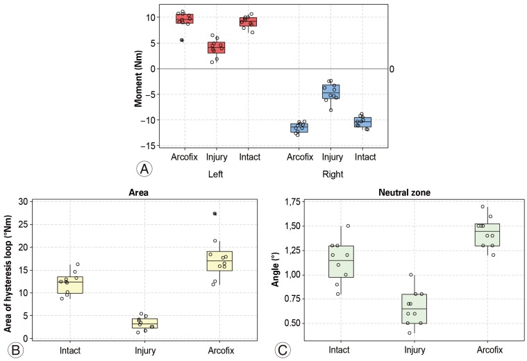
Box plot of (A) the maximum values of moment, (B) the area of fourth hysteresis loop, and (C) the values of neutral zone. Circle symbols mean individual values.
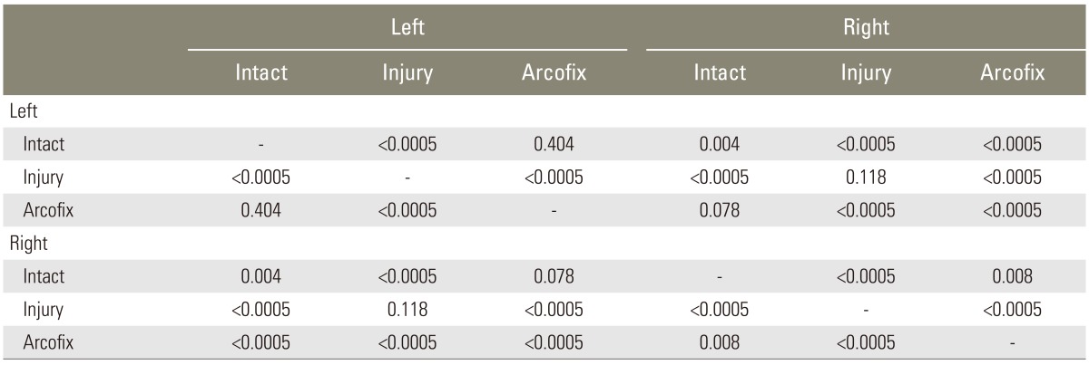
A p-values of paired t-test
Statistically significant differences were found between the intact and injured specimens and the injured and implanted samples with respect to both the positive and negative twisting angles. The torque magnitude decreased in the injured specimens to about 45% of the value of the implanted and intact specimens. The different behaviour of the specimens was also confirmed in the intact and implanted specimens with regard to the positive and negative twisting angles. This indicates an asymmetric behaviour of the sample when rotation occurs. No statistically significant differences were found between the intact and implanted specimens. The implant therefore returned the stability of the injured sample to its physiological state.
2. Area of hysteresis loop
Another parameter that was evaluated was the area of the hysteresis loop. The area corresponds to the deformation energy which is dissipated during the cycle. It describes the viscoelastic and/or plastic behaviour of the specimen [7]. The values were recorded only during the fourth load cycle. The reason for this procedure was to minimize the viscoelastic effects and to obtain repeatable results. The measured values for the fourth loading cycle are summarized in Table 3. A box plot was used for graphical comparison (Fig. 5B).
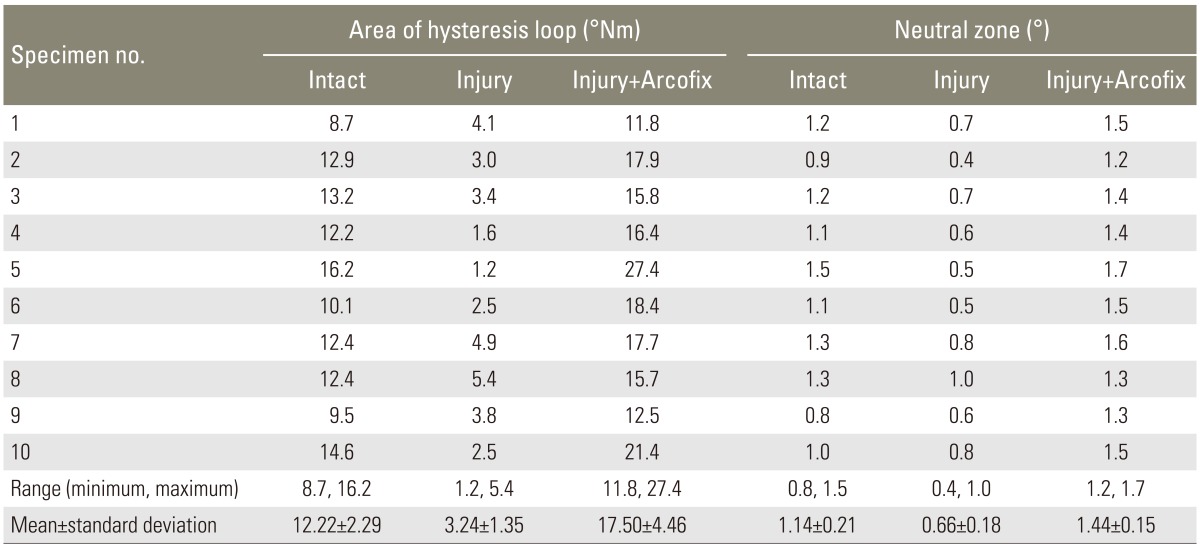
Area of hysteresis loop and neutral zone on the fourth load cycle
A paired t-test was used to compare the different states of the samples. The calculated p-values are summarized in Table 4. The test of normality at the significance level 5% rejected the hypothesis that the data follow a normal distribution. The statistical evaluation showed a statistically different value of the hysteresis loop area for the fourth cycle in each individual state. In the case of instability, the area decreased to 33% of the physiological value. For the implanted sample, the area increased to 170% of the physiological value.

A p-values of paired t-test for area of hysteresis loop
3. The neutral zone
The neutral zone is part of the range of intervertebral motion which is characterized by minimal intervertebral resistance [8]. Several studies have shown that the neutral zone is the parameter that correlates with other parameters indicating the stability or instability of the spinal system [89]. The measured values for the fourth loading cycle are summarized in Table 3. A box plot was used for graphical comparison (Fig. 5C).
A paired t-test was used to compare the different states of the samples. The calculated p-values are summarized in Table 4. The test of normality at the significance level 5% rejected the hypothesis that the data come from a normal distribution. A statistical evaluation showed statistically different values of the angle of the neutral zone for the fourth cycle in each individual state. In the case of instability, the value decreased to 67% of the physiological value. After stabilization, the value of the neutral angle increased to 113% of the physiological value.
Discussion
For certain types of fractures or other disorders of the anterior column of the spine (including tumours, spondylodiscitis), isolated anterior stabilizing intervention is recommended when we perform a partial or complete corpectomy with the substitution of a vertebral body by a bone graft or other type of implant [123456]. We use combined anterior and posterior stabilization, especially in cases when it is necessary to first influence a kyphotic deformity from behind and then to create conditions in the front for healing (desis). The new generation of plates with fixed angles enable a repositioning manoeuvre even when we use an isolated anterior approach. In the final position, the plate is locked and forms a rigid structure stabilizing the affected segment of the spine.
Laboratory testing of spinal implants constitutes a very important part of the implementation of new materials and techniques into clinical practice. The most frequently used animal models are sheep, lambs, and pigs [1011]. The disadvantage of the sheep or lamb spine is its relatively smaller size compared to a human spine. In terms of the porcine spine, at an appropriate age, we can get samples of a size fully comparable to human samples. Most studies describe a higher mobility of the spinal segment in animal samples compared to human samples. The authors explain that this is due to the biological age of the samples. While animal models are acquired from young, often still immature individuals, human samples are usually from cadavers of an older population [101112]. In our opinion, it can be assumed that in the case of younger patients, the biomechanical behaviour of the samples would more approximate the animal model. According to the majority of authors, the biomechanics of the spinal sample of the pig is very similar to that of humans, and is therefore well-suited to in vitro testing [10111213].
Hitchon et al. [3], in his study, compared three types of ventral stabilization systems on human cadaver samples: the anterior thoracolumbar locking plate, the Kaneda fixator rod, and the Z-plate. In intact samples, the researchers did not find any significant differences between these different implants. After bilateral facetectomy, a comparable instability of all the implants developed. In the simulation of a corpectomy and substitution of the vertebral body with a graft, the greatest strength was achieved by the Kaneda system due to the possibility of graft compression and bicortical introduction of screws. On 30 veal samples, Flamme et al. [2] biomechanically tested differences between the isolated posterior (SOCON, Aesculap, Tuttlingen, Germany) and isolated anterior (MACS TL, Aesculap) stabilization. He did not find any differences in the rotational and lateral bending loads. In the flexion/extension load, dorsal stabilization was significantly more stable. Faro et al. [1] tested 22 lamb samples: he performed a corpectomy of L3 with the graft replacement and subsequent stabilization by the ATL-Z plate (10 samples; Medtronic, Sofamor Danek, Memphis, TN, USA) or by the Antares rod system (12 samples; CD HORIZON, Medtronic). He tested the samples with flexion, extension, bending, and rotational loads. Samples stabilized by means of the fixator rod showed a higher bending strength compared to the plate. In the rotational load, there was no statistical difference between the two systems. Both systems demonstrated sufficient primary stability. Disch et al. [14] tested 12 human specimens and compared the stability of the spinal segments fixed by Arcofix or MACS implant. The Arcofix system showed superior stability in axial rotation and lateral bending compared to MACS.
In our study, we tested Arcofix, a modern implant which stabilizes the anterior column of the spine using screws with fixed angles. We have proven that the biomechanical parameters achieved by the stabilization of the damaged spinal segment are comparable with the behaviour of the intact sample, a result similar to that of other authors [14]. Nevertheless, more tests in different loading modes must be conducted in order to determine the complete biomechanical performance of the Arcofix implant.
Conclusions
The aim of our in vitro study was to compare the mechanical properties of the spinal segment in the intact state, destabilized, or injured state and the state after stabilization with Arcofix implant. The problem was solved by using the experimental modelling Zwick testing machine, on which the loading states were simulated. Ten test samples were prepared for the experiment. Their respective mechanical properties were described by the value of force couple needed to twist the specimen during the applied tensile force of 200 N, the size of hysteresis loop area, and the value of the neutral zone. Statistical analysis of measured results confirmed the hypothesis of different behaviour depending on the state (intact, injured, or implanted) of the samples. The analysis did not show different mechanical behaviours of intact and stabilized specimens with respect to the couple moment. The hysteresis loop areas and the size of the neutral zone in these states were statistically different. By stabilizing the injured spinal segment with an Arcofix implant, the behaviour was closer to the physiological state. The experimentally determined data were statistically processed using Minitab 15 Statistical Software (Minitab Inc., State College, PA,USA).
Acknowledgments
The present work has been supported by the research project with Reg. No. FSI-S-11-12/1225 and the European Regional Development Fund in the framework of the research project NETME Centre under the Operational Programme Research and Development for Innovation. Reg. No. CZ.1.05/2.1.00/01.0002, ID code: ED0002/01/01, project name: NETME Centre-New Technologies for Mechanical Engineering.
Notes
Conflict of Interest: No potential conflict of interest relevant to this article was reported.