Percutaneous Pedicle Screw Fixation of a Hangman's Fracture Using Intraoperative, Full Rotation, Three-dimensional Image (O-arm)-based Navigation: A Technical Case Report
Article information
Abstract
Surgical treatment of a hangman's fractures is technically demanding, even when using the standard open procedure. In this case report, a type II hangman's fracture was treated by percutaneous posterior screw fixation, without a midline incision, using intraoperative, full rotation, three-dimensional (3D) image (O-arm)-based navigation. A 48-year-old woman was injured in a motor vehicle accident and diagnosed with a unilateral hangman's fracture associated with subluxation of the C2 vertebral body on C3. After attaching the reference arc of the 3D-imaging system to the headholder, the cervical spine was screened using an O-arm without anatomical registration. Drilling and screw fixation were performed using a guide tube while referring to the reconstructed 3D-anatomical views. The operation was successfully completed without technical difficulties or neurovascular complications. This percutaneous procedure requires less dissection of normal tissue, which may allow earlier recovery. However, further validation of this procedure for its effectiveness and safety is required.
Introduction
Hangman's fractures are characterized by an avulsion fracture through the neural arch of the axis, with or without a fracture/dislocation of the C2 vertebral body (VB) on C3 [1]. Treatment of this disorder can be either conservative or surgical, depending on the type of fracture and the symptoms. In some cases, transpedicular osteosynthesis may offer the most effective treatment as it provides a compression force against the fracture lesion and prevents the motion segments from fusion [2]. However, this surgery requires extensive exposure to insert the screw at a high degree angle on the axial plane through a midline incision with a forceful paraspinal retraction. Moreover, pedicle screw fixation of the upper cervical spine remains challenging because of the associated risk to neurovascular structures and the highly variable anatomy of the pedicle within this region [3]. Under these demanding conditions, intraoperative, three-dimensional (3D) image-based navigation may be advantageous because it improves the accuracy of screw placement [4-8] and offers the possibility of using a percutaneous technique. In this article, we present a case of a hangman's fracture treated with a percutaneous procedure using intraoperative, full rotation, 3D image (O-arm)-based navigation.
Case Report
A 48-year-old woman was injured in a motor vehicle accident and complained of pain in her neck and both ears that onset immediately after the accident. She was neurologically normal except for temporary mild numbness of the upper extremities. Radiographs revealed a pedicular fracture of the axis with subluxation of the C2 VB on C3 (Fig. 1A). Computed tomography (CT) scanning revealed a unilateral hangman's fracture involving the vertebral foramen and a laminar fracture on the opposite side (Fig. 1B). A sagittal CT scan revealed displaced fragments on the posterior edge of the C2 VB (Fig. 1C). Magnetic resonance imaging revealed the absence of spinal cord compression while CT angiography ruled out injuries or occlusion of the vertebral artery (VA) at the C2-C3 level (Fig. 1D).

Preoperative injury characteristics. (A) Lateral radiograph showing 18 degree angulation of the C2 and C3 vertebral bodies. (B) Axial computed tomography (CT) showing exact fracture configuration. (C) Sagittal CT scan showing the fracture fragment in the spinal canal. (D) CT angiographic image ruling out injuries or occlusion of the vertebral artery.
1. Surgical technique
The patient was placed in a prone position on a carbon-fiber, radiolucent operating frame (Jackson table, Mizuho OSI, Union City, CA, USA) after routine intubation. Her head was fixed using a carbon-fiber Mayfield head clamp with the neck slightly extended. A reference arm was fixed to the head clamp. The patient's cervical spine was screened using an O-arm (Medtronic, Minneapolis, MN, USA) (Fig. 2A), and the acquired images were transferred to the StealthStation (Medtronic). The skin entry point was determined as 5 cm lateral from the midline and 4 cm caudal from the C2 spinous process; this was estimated through the placement of an image-guided probe mounted onto an array on the skin's surface that matched the preplanned screw trajectory on the computer workstation monitor. An initial incision of 10 mm was made at this point, and the trapezius, splenius capitis, and semispinalis capitis muscles were divided along the direction of the fibers using long straight forceps. An image-guided sleeve with an awl was inserted through the subcutaneous tissues and muscles until its sharpened tip engaged the entry point at the C2 lamina. A 2.8-mm drill bit was then inserted into the tube, and a pilot hole was made under image guidance. The drill bit was then removed, and a 1.5-mm sharp-tipped guidewire was inserted into the pilot hole through the guide tube. The guidewire was carefully advanced into the C2 VB with a manual hand drill using 3D fluoroscopy-based navigation (Fig. 2B). After the guidewire reached the distal cortex of the C2 VB, a screw path was made using a cannulated drill bit that slid over the guidewire (Fig. 2C). A 32 × 4.0-mm, self-tapping, cannulated lag screw was inserted over the guidewire and tightened to increase the lag effect and reduction. Finally, the incision was closed with a single fascial suture and two skin sutures (Fig. 2D). Before extubation, CT angiography ruled out the possibility that occlusion of the VA had resulted from compression of the transverse foramen (Fig. 3). Postoperatively, the patient wore a headmaster collar for 3 months. Proper realignment and bony union of the C2-C3 vertebrae was documented 2 years after surgery (Fig. 4).

Intraoperative images showing successful percutaneous posterior cervical fixation. (A) Patient inside the O-arm system and the attachment of the reference arc to the halo ring. (B) Insertion of the guidewire into the C2 vertebral body with a manual hand drill using navigation. (C) Intraoperative images produced by the navigation system. Trajectory used to guide the direction and depth of drilling. (D) Postoperative skin incision (10 mm) after percutaneous posterior cervical fixation.
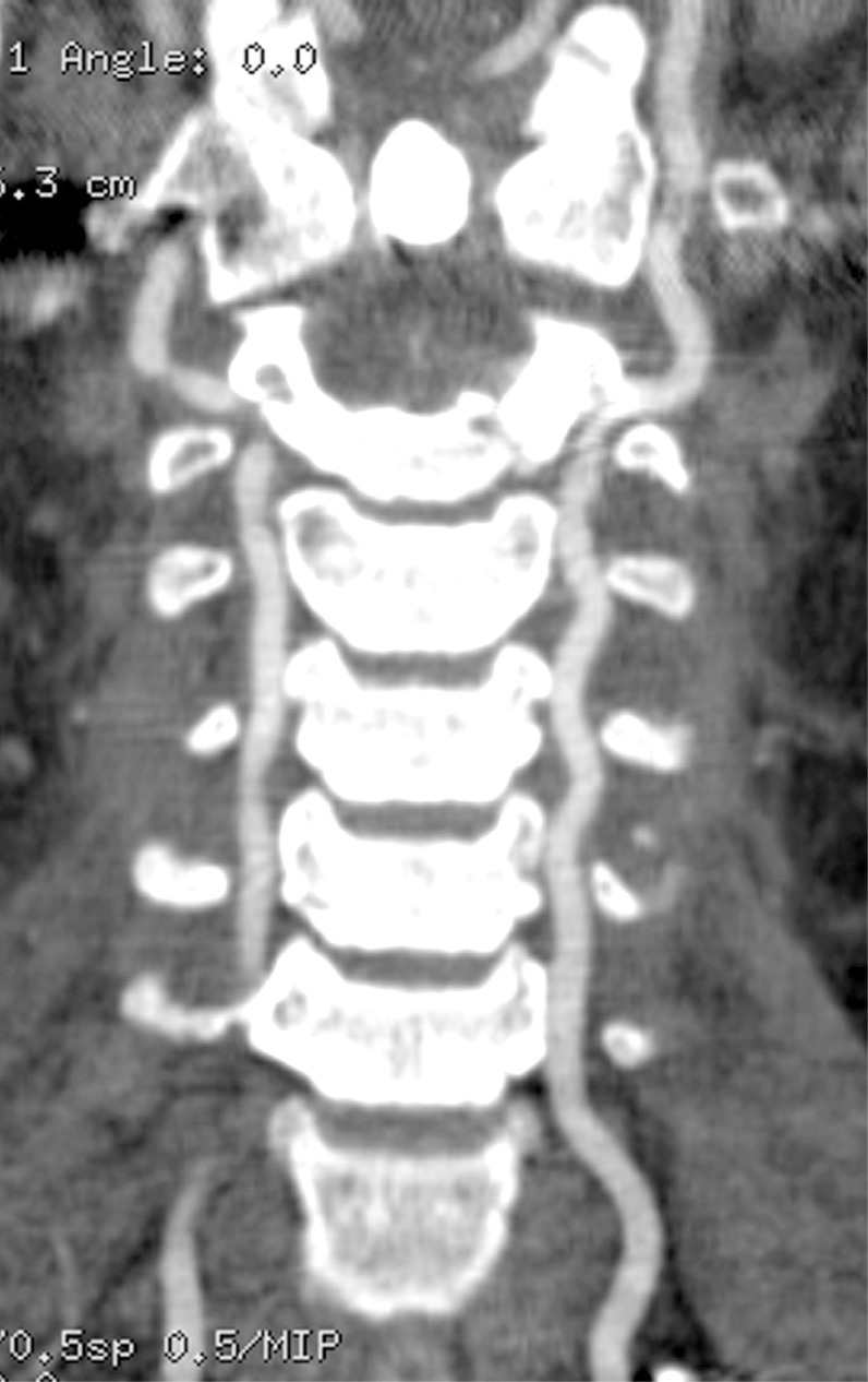
Postoperative computed tomography angiography. No occlusion of the vertebral artery arose from compression of the transverse foramen.

Lateral radiograph (A), axial computed tomography (CT) scan (B), parasagittal CT scan (C), and coronal CT scan (D) performed 2 years after surgery showing proper alignment and bony union.
Discussion
Percutaneous screw fixation is increasingly being used as a minimally invasive fixation method for treating lumbar and thoracic spine disorders. However, this method is rarely used to treat the cervical spine because of its small dimensions and proximity to neurovascular structures. Holly and Foley [4] reported on the percutaneous placement of a posterior cervical screw in their cadaver study and achieved highly accurate screw placement using 3D image-based navigation. They did not observe any serious injury to the VA or spinal cord in the cadavers following this procedure. Thus, intraoperative, 3D image-based navigation is required for the percutaneous procedure, while preoperative, 3D-CT-based navigation is inappropriate because of the need for point or surface registration with open exposure. With regard to intraoperative, 3D image-based navigation, we have previously reported on the use and limitations of the Iso-C3D-based (Siemens, Medical Solutions, Erlangen, Germany) and O-arm-based navigation systems separately for the placement of cervical pedicle screws (CPSs) [5,6]. In particular, O-arm offers high-resolution 2D/3D images that facilitate the accurate and safe insertion of CPS via high-quality navigation, along with other substantial benefits towards cervical spinal instrumentation. These high-resolution images are required for the application of percutaneous screw fixation to the cervical spine. Furthermore, the correct position to fix the reference arc is thought to be the next challenge related to navigation inaccuracy and the complete percutaneous procedure. In general, when using intraoperative, 3D image-based navigation, the reference arc is fixed to the spinal level being instrumented. Sugimoto et al. [7] reported a case of hangman's fracture treated using the percutaneous procedure with a small midline incision. They used Iso-C3D-based navigation and the reference arc was attached to the spinous process of the axis. Contrarily, in the present case, the reference arc was attached to the halo ring because of the instability of the C2 spinous process. Under the current guidelines for image-guided placement of instrumentation to the upper cervical spine, attaching a reference arc to the headholder, such as the halo ring, is a controversial topic. However, Nottmeier and Young [8] reported that the image-guided placement of occipitocervical instrumentation using a reference arc attached to a headholder is safe and accurate as long as all the screw holes are drilled with image guidance before tapping the bone and placing the instrumentation [8]. They also pointed out the intersegmental movement that can occur when tapping the holes or placing the screws, as well as the spreading force of the posterior cervical wound caused by the retractor system. Percutaneous screw fixation, without attaching the reference arc to the instrument level, was free from this spreading force induced by the retractor system.
There are several limitations to the clinical application of this technique. First, this technique is limited to certain types of cervical pathology, such as the cervical trauma typically associated with hangman's fractures. Although most type I fractures can be treated conservatively, it has been suggested that type IIa and type III fractures require surgery [9]. Rajasekaran et al. [10] described intraoperative, 3D image-based navigation for transpedicular screw fixation as an effective standard open procedure for treating type II hangman's fractures. Type III fractures, combined with bilateral facet dislocation, often require open reduction and fusion of the C2 and C3 vertebrae. Thus, type II and IIa fractures present optimal conditions for the application of the percutaneous technique demonstrated in this case. Second, this technique requires a more detailed preoperative examination of the cervical region than the open procedure because of the varied morphological characteristics of cervical pedicles and the vertebral artery. Moreover, when the fracture involves the transverse foramen, bringing the fracture back into anatomical alignment may, rarely, compromise the vasculature. In order to prevent this complication, intraoperative CT angiography can provide early detection. Finally, this technique requires thorough knowledge of spinal anatomy and a great deal of experience in open procedures. If an unexpected complication arises, such as serious neurovascular injury, the surgeon must be able to immediately revert to an open method. Despite these limitations, percutaneous posterior screw fixation has several advantages. Direct access to the target site is the main advantage. Because the entry point of the pedicle screw is deep and angulated in the axial plane, it is easier to insert the screw percutaneously than it is in the open procedure using the midline approach. The force of the paraspinal muscles toward the center from the far lateral side can cause the misinsertion of screws. Moreover, the minimal invasiveness of this method can result in reduced operative time, blood loss, postoperative pain and risk of infection, leading to a much quicker recovery. We believe that the percutaneous technique for posterior cervical screw fixation has many advantages and is reliable for treating carefully selected patients, assuming that the surgeon has sufficient experience of performing open surgeries. The preliminary results of this case are promising, but proper evaluation will require more extensive studies.