The “Skipped Segment Screw” Construct: An Alternative to Conventional Lateral Mass Fixation–Biomechanical Analysis in a Porcine Cervical Spine Model
Article information

Abstract
Study Design
Cadaveric biomechanical study.
Purpose
We compared the “skipped segment screw” (SSS) construct with the conventional “all segment screw” (ASS) construct for cervical spine fixation in six degrees of freedom in terms of the range of motion (ROM).
Overview of Literature
Currently, no clear guidelines are available in the literature for the configuration of lateral mass (LM) screwrod fixation for cervical spine stabilization. Most surgeons tend to insert screws bilaterally at all segments from C3 to C6 with the assumption that implants at every level will provide maximum stability.
Methods
Six porcine cervical spine specimens were harvested from fresh 6–9-month-old pigs. Each specimen was sequentially tested in the following order: intact uninstrumented (UIS), SSS (LM screws in C3, C5, and C7 bilaterally), and ASS (LM screws in C3–C7 bilaterally). Biomechanical testing was performed with a force of 2 Nm in six degrees of freedom and 3D motion tracking was performed.
Results
The two-tailed paired t-test was used for statistical analysis. There was a significant decrease in ROM in instrumented specimens compared with that in UIS specimens in all six degrees of motion (p<0.05), whereas there was no significant difference in ROM between the different types of constructs (SSS and ASS).
Conclusions
Because both configurations provide comparable stability under physiological loading, we provide a biomechanical basis for the use of SSS configuration owing to its potential clinical advantages, such as relatively less bulk of implants within a small operative field, relative ease of manipulating the rod into position, shorter surgical time, less blood loss, lower risk of screw-related complications, less implant-related costs, and most importantly, no compromise in the required stability needed until fusion.
Introduction
Lateral mass (LM) screw fixation is a common technique for posterior stabilization of the subaxial cervical spine. However, no clear guidelines are available for the configuration of LM screw-rod fixation, and most surgeons tend to insert screws bilaterally at all segments from C3 to C6 with the assumption that implants at every level will provide maximum stability. This can lead to problems, such as an excessive bulk of implants within a small operative field, difficulties in manipulating the rod into position because of screw crowding, increase in surgical time, more blood loss, greater risk of screw-related complications, and greater implant-related costs.
We proposed a “skipped segment (SS)” LM screw-rod fixation configuration. We anticipated a potential reduction in the occurrence of all of the aforementioned problems, in addition to providing surgeons a biomechanical basis to choose an alternative implant configuration, with the ultimate goal of providing adequate stability at physiological loads in the cervical spine. We compared the SS screw (SSS) construct with the conventional “all segment screw” (ASS) construct for posterior stabilization of the cervical spine in terms of stability at physiological loading.
Materials and Methods
This study was approved by the Institutional Review Board (Irb no., 8844). Six porcine cervical spine specimens, including the occiput and first thoracic vertebra, were freshly harvested from 6–9-month-old pigs, and muscle attachments were carefully cleared off while retaining just the discoligamentous structures. Plain radiographs and bone densitometry scans were performed to rule out any gross skeletal pathology. All specimens were packaged immediately in double-thickness plastic bags and stored at −20℃. Each specimen was sequentially tested in the following order: intact uninstrumented (UIS), SSS (LM screws in C3, C5, and C7 bilaterally), and ASS (LM screws in C3–C7 bilaterally) (Fig. 1). LM screws were inserted as per the Magerl technique [1]; the entry point for screw insertion was located slightly medial and rostral to the midpoint of LM. The direction of the screw was 25° lateral in the axial plane and parallel to the facet joint in the sagittal plane. A 2.0-mm diameter, high-speed drill bit and a 3.5-mm diameter adjustable cancellous tap were used to prepare pilot holes before screws were inserted. All screws were made of titanium with a polyaxial head design and were 3.5 mm in diameter. The average length of each screw was 16 mm. Screws of appropriate length were used in each specimen to achieve bicortical purchase. Titanium rods (4 mm in diameter and of appropriate length) were used bilaterally to build the construct. The ends of the specimen were trimmed and fixed into bone cement potted to fit into the Crawford frame [2]. Each specimen was given a pure unidirectional bending moment in flexion–extension, right–left lateral bending, and clockwise–anticlockwise torsion using a system of pulleys and cables attached to the fixtures in a universal testing machine. 3D motion tracking sensors (G4 system, Polhemus, Colchester, VT, USA) were used to record the range of motion (ROM) in six degrees of freedom. A testing force was applied in each test direction at a displacement controlled rate of 2 Nm at 5 mm/sec. Neutral point coordinates were recorded using the motion tracker before the start of loading for each test direction. Three preconditioning load cycles were applied to remove the slack from the system. At the end of the third loading cycle, coordinates were recorded again. The biomechanical testing was repeated using the same test protocol and the coordinates were recorded for each specimen. The testing device was reconfigured after each test direction. The elastic zone (EZ) was defined as the peak displacement from the initial neutral position to maximum load, and the neutral (NZ) represented the motion from the initial neutral position to the unloaded position at the beginning of the third cycle. Segmental ROM was calculated as the sum of NZ and EZ (NZ+EZ=ROM) and was represented as a peak total ROM (Euler angles rotation) at the third loading cycle. At the end of sequential testing, each specimen was tested for failure mechanism.

(A) Specimen with the SSS configuration. (B) Specimen with the ASS configuration. Both ends of the specimen are covered with bone cement to facilitate mounting onto the frame. SSS, skipped segment screw; ASS, all segment screw.
Failure mechanism was studied by applying a gradually increasing force up to 12 Nm at 5 mm/sec, which is six times the force exerted during physiological loading at the cervical spine and almost twice the physiological load experienced at the lumbar spine [3]. Each specimen was carefully monitored as the force was increased until 12 Nm, and any stretch in the ligaments or implant pullout was recorded. ROM values in each test direction were compared between SSS and ASS specimens and both constructs were compared with UIS specimen. A single-tailed paired t-test of significance was used for statistical analysis (IBM SPSS Statistics ver. 23, IBM Co., Armonk, NY, USA).
Results
The mean total ROM in flexion-extension, left-right lateral bending, and left-right torsion axes were 38.1°, 34.4°, and 13.2°, respectively, for UIS; 4.3°, 8.5°, and 3.9°, respectively, for SSS; and 4.5°, 5.6°, and 3.4°, respectively, for ASS specimens (Table 1). The ratio of ROM in NZ and EZ was consistent across all three constructs. There was a significant decrease in the mean segmental motion in NZ and EZ in all six directions when comparing instrumented (SSS and ASS) and UIS specimens (p<0.05) (Fig. 2). When comparing both instrumented specimens (SSS and ASS), there was no significant difference in ROM (p>0.05) (Table 2). Compared with UIS specimens, there was a 85.4% and 87.8% decrease in ROM in SSS and ASS specimens (Fig. 3). These results highlighted the fact that both instrumentation techniques had comparable rigidity when compared with each other, while both were significantly more rigid compared with the UIS specimen.

Mean values of ROM and NZ in degrees (SD) for un-instrumented, skipped segment and all segment configuration in 6 degree of freedom
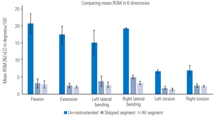
Comparison of ROM for UIS, SSS, and ASS configurations in six degrees of freedom. ROM, range of motion; UIS, uninstrumented; SSS, skipped segment screw; ASS, all segment screw; Nz, neutral zone; EZ, elastic zone; SD, standard deviation.
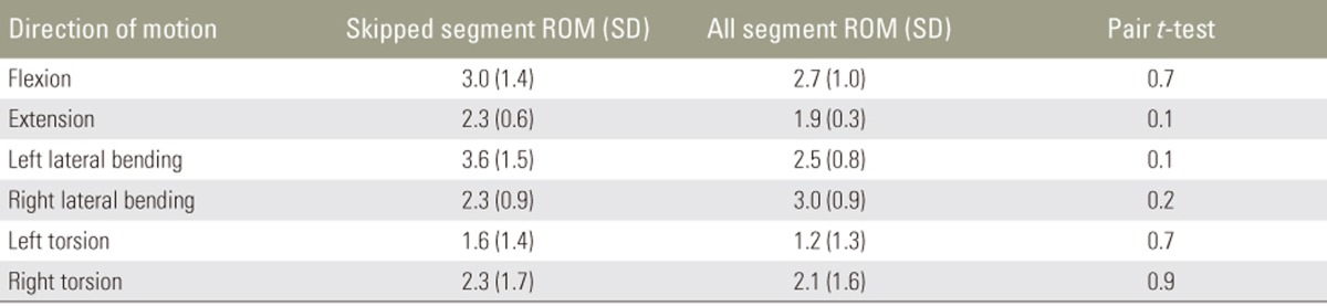
Comparison of ROM in degrees (SD) between skipped segment and all segment configuration with paired t-test of significance
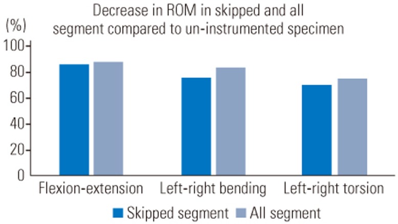
Decrease of ROM in flexion-extension, left-right bending, and left-right torsion axes in percentage for SSS and ASS specimens compared with those for UIS specimens. ROM, range of motion; SSS, skipped segment screw; ASS, all segment screw; UIS, uninstrumented.
While studying the mechanisms of construct failure, we found that failure occurred in two specimens, each in ASS and the SSS constructs. All failures were observed in axial rotation at the cervicothoracic junction.
Discussion
Roy-Camille et al. [4] introduced the LM screw-and-plate system in the late 1980s, which could be considered as the precursor to the current-day screw-rod systems. Numerous advances in the implant design have resulted in LM screws becoming the technique of choice for posterior stabilization of the cervical spine [5].
Although convention has dictated that LM screws be inserted at every level within the surgical construct, we hypothesized that alternate segment fixation would provide a comparable degree of biomechanical stability, ultimately providing adequate stress shielding under physiological loading until fusion. Our comparison of multisegmental ROM and NZ properties of SSS and conventional ASS construct between C3 and C7 showed comparable properties across the testing protocol. Our results showed that the SSS construct as well as the traditional ASS construct had significantly decreased ROM and NZ compared with the UIS construct (p<0.05). When compared to each other, the SSS construct did not have any significant difference in ROM and NZ compared with the conventional ASS construct (p>0.05). Therefore, our findings suggested that the SSS construct provided comparable rigidity, thereby providing adequate stress shielding to the conventional ASS construct under physiological loading. Our results provide a biomechanical basis to adopt this technique in clinical scenarios.
We used bicortical screws in our testing protocol as these constructs have been shown to be stiffer than unicortical screw constructs after multilevel laminectomy [6]. However, unicortical LM screws have been shown to be comparable with bicortical LM screws when the posterior elements are intact [7]. In the clinical scenario, it has been reported that unicortical LM screws have lower rates of complications than bicortical screws [78]. The aim of our study was not to compare the comparative stiffness of unicortical and bicortical screws, and we believe that the choice between the two in the clinical scenario is best left to the treating surgeon's discretion.
Although we used LM screws at the C7 level in our study, currently, most surgeons prefer C7 pedicle screws over LM screws because the C7 LM is smaller than the upper subaxial LM and entry of the vertebral artery into the foramen transversarium at C6 allows an improved safety profile for a C7 pedicle screw [19]. One potential limitation of this study was that LM screws were used at the C7 level in all specimens because of the convenience of screw and rod insertion without the help of fluoroscopy.
Although the human cadaveric spine model would be ideal for testing, their procurement is difficult. On the contrary, porcine spines are readily available and have comparable properties and anatomy to the human c spine. Porcine spine models have been used as a substitute for the human cadaver and validated in previous biomechanical studies [101112]. One potential drawback observed in all biomechanical studies is a lack of consideration for the stability provided by the surrounding muscles and soft tissue in in vivo conditions. We believe that it will further enhance the stability provided by the spinal implants. In addition, it is common to perform a cervical fixation with decompression laminectomy, which involves disruption of the posterior elements (ligaments, laminae, spinous process, and sometimes facet joints). This is a potential drawback of the study, but we believe it could have a similar impact on the biomechanics of ASS and SSS constructs.
We also found that the Crawford frame [2] used for testing is modular, can incorporate various sizes of the specimen, gives reproducible and consistent results, and is a cost-effective method to conduct biomechanical studies. We did not conduct fatigue testing in this study because we believe that the role of these implants is to provide adequate stress shielding to avoid instability after decompression and we predict that these implants will not have any major role once fusion occurs in the long term. This study included analysis of the failure mechanism of both configurations with load application of 12 Nm, which is almost equivalent to six times the physiological load [3]. All failures occurred at the lower transition zone between the instrumented cervical spine and uninstrumented thoracic spine. It was noteworthy that all four failures occurred under axial rotation, indicating that rotational stresses create maximum pullout forces acting on the terminal screws of the construct and probably affect the integrity of the facet joints.
Our findings suggested that SSS LM screw constructs offer comparable mechanical stability and may offer secondary advantages, such as the use of fewer implants, easier rod insertion, and shorter surgical time. We believe that our findings provide a sound biomechanical basis for adopting this technique in most routine clinical scenarios where LM fixation for the subaxial cervical spine is being undertaken.
Conclusions
To the best of our knowledge, no such study in the literature has compared SSS configuration to ASS configuration. This study provides a sound biomechanical basis to use the SSS-rod configuration in clinical practice because of its potential advantages, such as relatively less bulk of implants within a small operative field, ease of manipulating the rod into position, shorter surgical time, less blood loss, lower risk of screw-related complications, and lower implant-related costs. Our study also highlighted that the most vulnerable location for failure is the transition zone between the instrumented and uninstrumented spine and the most common mechanism of failure was in rotatory motion.
Notes
Conflict of Interest: No potential conflict of interest relevant to this article was reported.