Asian Spine J Search

CLOSE


Asian Spine J > Volume 11(2); 2017 > Article
Lee, Tan, Chan, and Kwan: Surgical Morphometry of C1 and C2 Vertebrae: A Three-Dimensional Computed Tomography Analysis of 180 Chinese, Indian, and Malay Patients

Abstract

Study Design

Clinical imaging study.

Purpose

To study the surgical morphometry of C1 and C2 vertebrae in Chinese, Indian, and Malay patients.

Overview of Literature

C1 lateral mass and C2 pedicle screw fixation is gaining popularity. However, there is a lack of C1–C2 morphometric data for the Asian population.

Methods

Computed tomography analysis of 180 subjects (60 subjects each belonging to Chinese, Indian, and Malay populations) using simulation software was performed. Length and angulations of C1 lateral mass (C1LM) and C2 pedicle (C2P) screws were assessed.

Results

The predicted C1LM screw length was between 23.2 and 30.2 mm. The safe zone of trajectories was within 11.0°±7.7° laterally to 29.1°±6.2° medially in the axial plane and 37.0°±10.2° caudally to 20.9°±7.8° cephalically in the sagittal plane. The shortest and longest predicted C2P screw lengths were 22.1±2.8 mm and 28.5±3.2 mm, respectively. The safe trajectories were from 25.1° to 39.3° medially in the axial plane and 32.3° to 45.9° cephalically in the sagittal plane.

Conclusions

C1LM screw length was 23–30 mm with the axial safe zone from 11° laterally to 29° medially and sagittal safe zone at 21° cephalically. C2P screw length was 22–28 mm with axial safe zone from 26° to 40° medially and sagittal safe zone from 32° to 46° cephalically. These data serve as an important reference for Chinese, Indian, and Malay populations during C1–C2 instrumentation.

Introduction

Posterior fixation using C1 lateral mass and C2 pedicle screws is gaining popularity among spine surgeons as the preferred method for C1–C2 instrumentation because of its superior biomechanical stability compared with that of other fixations methods [12]. Considering the close proximity of important vascular and neural structures, detailed knowledge regarding the anatomy and morphometric features of C1 and C2 is necessary to avoid potentially fatal complications. Young et al. reported that mistaking the ponticulus posticus for just a broad posterior arch of the atlas during C1 lateral mass screw placement could cause injury to the vertebral artery [3]. The presence of high-riding vertebral artery (HRVA) with a concurrent small pedicle is also a risk factor for vertebral artery injury [4]. Vascular anatomy, safety, and feasibility of the C1 lateral mass screw and C2 pedicle screw have not been thoroughly investigated among the Asian population [45678]. Hence, this study was designed to determine the surgical morphometry of the C1 lateral mass and C2 pedicle among Chinese, Indian, and Malay individuals who represent majority of the population belonging to Southeast Asia [9].

Materials and Methods

Ethical approval was obtained for this study. Computed tomography (CT) scans were retrospectively retrieved. The inclusion criteria were adults aged more than 18 years having undergone a cervical spine CT scan regardless of the reason underlying need for the scan. The exclusion criteria were poor quality images and pathologies involving the C1–C2 region, such as a congenital anomaly, a tumor, an infection, a fracture, inflammatory arthritis, and severe degeneration. The male to female ratio was 1:1 with average age of 50.6±16.4 years. Eventually, there were 60 subjects from each ethnic group (Chinese, Indian, and Malay).
Using Mimics ver. 15.0 (Materialise, Leuven, Belgium), the CT images of each subject were converted into 3-dimensional (3D) models and resliced in the direction of the preferred screw entry point and trajectories. The following landmarks and measurements were identified and measured:

1. Parameters for C1LM screw

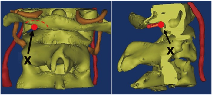
The entry point described by Currier and Yaszemski [10] was applied. During surgery, this point is created using a 2-mm burr in the lower portion of the posterior arch and drilled into the lateral mass below the vertebral artery groove. This entry point is represented as X (Fig. 1).
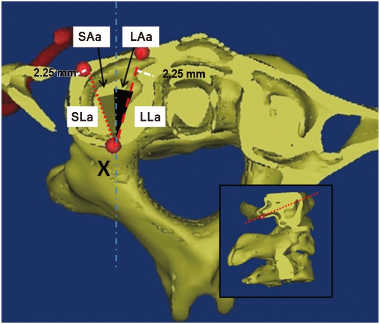
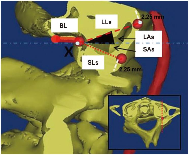
For measurements in the axial plane, the 3D-models were resliced in the neutral sagittal plane of C1LM (Fig. 2). Likewise, when sagittal measurements were obtained, the 3D models were resliced in the vertical axis of C1LM (Fig. 3).

1) Length

(1) S length (SL) is the shortest distance from X to the anterior cortex of C1, with an allowance of 2.25 mm (accounting for half of the diameter of a 4.5-mm C1LM screw) from the cortices to avoid cortical breach.
  • SLa refers to distance in the axial plane (Fig. 2)

    SLs refers to distance in the sagittal plane (Fig. 3).
(2) L length (LL) is the longest distance from X to the anterior cortex of C1, with an allowance of 2.25 mm from the cortices.
  • LLa refers to distance in the axial plane (Fig. 2)

    LLs refers to distance in the sagittal plane (Fig. 3).
(3) Base length (BL) is the distance from the posterior arc to X measured in the sagittal plane (Fig. 3).

2) Trajectory

(1) S angle (SA) is the angulation for the shortest C1LM screw length.
  • SAa refers to the axial plane trajectory (maximum lateral angulation) (Fig. 2).

    SAs refers to the sagittal plane trajectory (maximum caudal angulation) (Fig. 3).
(2) L angle (LA) is the angulation for the longest C1LM screw length.
  • LAa refers to the axial plane trajectory (maximum medial angulation) (Fig. 2).

    LAs refers to the sagittal plane trajectory (maximum cephalad angulation) (Fig. 3).
(3) T angle (TA) is the summation of SA and LA.
  • TAa refers to the safe zone in the axial plane.

    TAs refers to the safe zone in the sagittal plane.

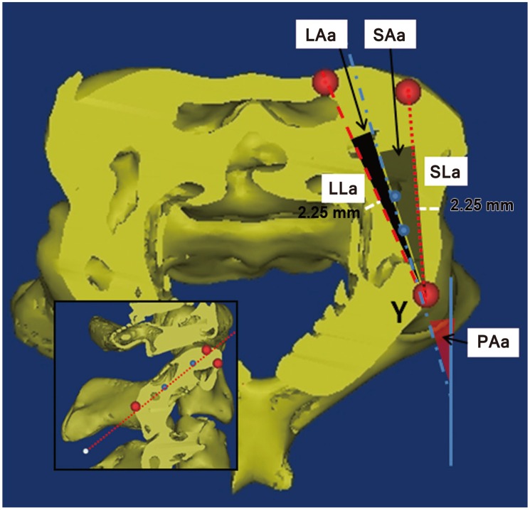
2. Parameters for C2P screw

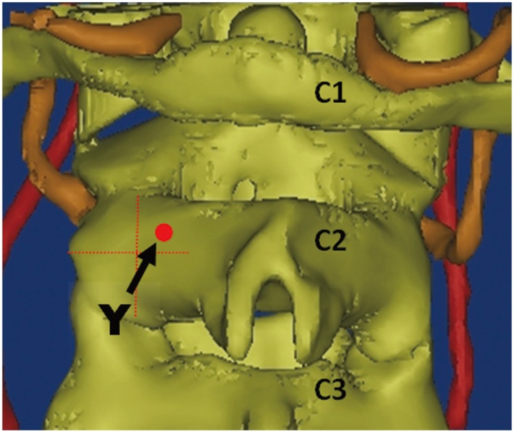
The entry point described by Goel and Laheri [11] and Harms and Melcher [12], which is located at the cranial and medial quadrant of the isthmus surface of the C2, was applied. This entry point is represented as Y (Fig. 4).
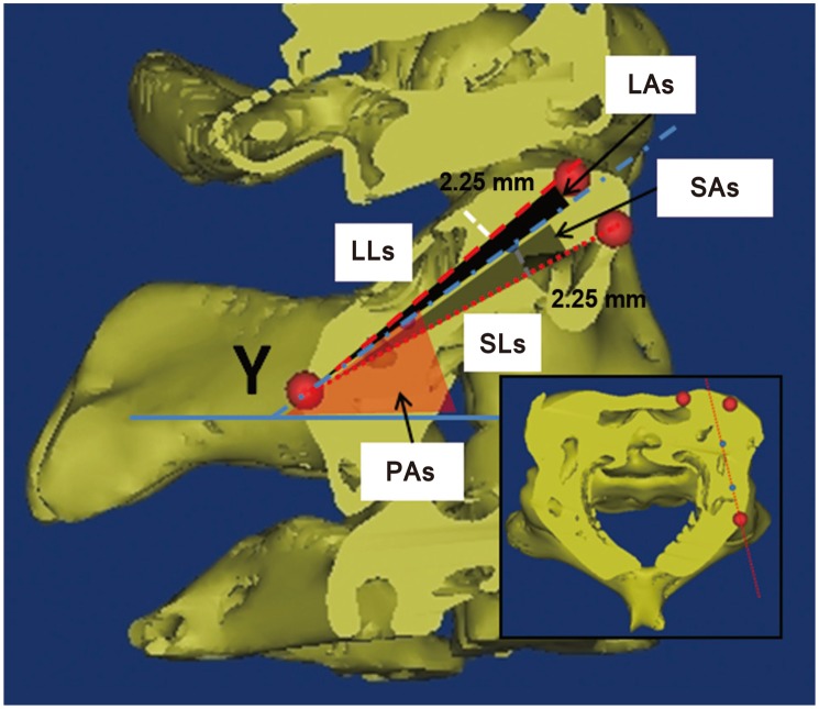
For measurement in the axial plane, the 3D models were resliced according to the axis of C2P in the sagittal plane (Fig. 5). Likewise, when sagittal measurements were obtained, the 3D models were resliced in the axis of C2P (Fig. 6).
When HRVA was present, the measurement would be excluded. HRVA is defined an isthmus of height ≤5 mm or internal height ≤2 mm [13].

1) Length

(1) SL is the shortest distance from Y to the anterior cortex of C2, with an allowance of 2.25 mm from the cortices.
  • SLa refers to the distance in the axial plane (Fig. 5).

    SLs refers to the distance in the sagittal plane (Fig. 6).
(2) LL is the longest distance from Y to the anterior cortex of C2, with an allowance of 2.25 mm from the cortices.
  • LLa refers to the distance in the axial plane (Fig. 5).

    LLs refers to the distance in the sagittal plane (Fig. 6).

2. Trajectory

(1) P angle (PA) is the angulation for C2P axis.
  • PAa refers to the pedicle axis in the axial plane (Fig. 5).

    PAs refers to the pedicle axis in the sagittal plane (Fig. 6).
(2) SA is the angulation for the shortest C2P screw length.
  • SAa refers to the axial plane trajectory (maximum lateral angulation) (Fig. 5).

    SAs refers to the sagittal plane trajectory (maximum caudal angulation) (Fig. 6).
(3) LA is the angulation for the longest C2P screw length.
  • LAa refers to the axial plane trajectory (maximum medial angulation) (Fig. 5).

    LAs refers to the sagittal plane trajectory (maximum cephalad angulation) (Fig. 6).
(4) T angle (TA) is the summation of SA and LA.
  • TAa refers to the safe zone in the axial plane.

    TAs refers to the safe zone in the sagittal plane.

Results

1. C1LM parameters

The mean length of screw outside the lateral mass (BL) was 8.5±1.4 mm. The mean shortest length within the lateral mass (SLa) was 14.7±1.6 mm with a lateral angulation (SAa) of 11.0°±7.7°. Medial angulation can increase screw length, with the longest screw length (LLa) of 21.7±2.3 mm and screw trajectory of 29.1°±6.2° medially. In the sagittal plane, cephalad angulations (LAs) of 20.9°±7.8° to caudal angulations (SAs) of 37.0°±10.2° with total trajectory angles (TAs) of 57.9°±9.0° were safe. The summary of C1LM parameters are shown in Table 1.

2. C2P parameters

We found 98 (27.2%) HRVAs in our study. The prevalence of HRVA for each ethnicity is summarized in Table 2. In the presence of HRVA, when the pedicle diameter was ≥4.5 mm, pedicle screw insertion was deemed feasible. These findings were excluded from the analysis because of violation of vertebral artery by the C2P screw.
For the 262 sides of C2 vertebra without any HRVA, the shortest length (SLa) was 24.1±3.2 mm with lateral angulation from the pedicle axis of 7.3°±4.1°. With increasing medial angulation, the longest screw length (LLa) of 28.5±3.2 mm can be achieved with medial angulation from the pedicle axis of 7.3°±4.1°. The mean pedicle axis in the axial plane (PAa) was 32.9°±4.9° with a safe window of 14.1°±5.7°. In the sagittal plane, cephalad screw angulations of 5.0°±3.1° to caudal angulations of 8.6°±2.9° from the sagittal pedicle axis were safe. The mean sagittal pedicle axis (Pas) was 40.9°±4.7° with a safety window of 13.6°±4.5°. A summary of C2P parameters is shown in Table 3.

Discussion

Various entry points for C1LM and C2P have been advocated [1614151617]. This has led to confusion with regards to the surgical morphometry of C1LM and C2P. Most morphometric studies have been performed in the Caucasian population; only a few have been performed in the Asian population [678]. To the best of our knowledge, this study is the only one comparing the differences between ethnicities.
Based on our measurements, the actual screw length to be used during surgery should be between 23 mm (BL+SLa) and 30 mm (BL+LLa). A longer screw length corresponded to a more medially angulated trajectory with a mean of 29.1°±6.2°. Maximum lateral angulation of 11.0°±7.7° was noted to be safe. In the sagittal plane, only cephalad angulation would have clinical importance according to Currier's technique [10] because the superior part of the posterior arch would prevent any caudal angulation. We noted that the maximum cephalad angulation was 20.9°±7.8° (Table 1).
No literature is available on surgical morphometric studies using Currier's entry point. Table 4 provides a summary of previous morphometric studies [781819202122]. Comparison between the studies might not be feasible because of variations in the methodology, screw diameter application, and the entry point. Tan et al. [8] and Ma et al. [7] studied the Chinese population. The other available studies were conducted in the Caucasian population. Ma et al. [7] fixed the angulations at 10° medially and 5° cephalically for length measurement. Our longest C1 screw length of 30 mm (BL+LLa) was similar to the study the length observed in the study conducted by Tan et al. [8] who used an entry point at the posterior arch of C1. Gebauer et al. [14] also used a posterior arch entry point for their morphometric study. The C1LM screw lengths in our study were shorter compared with those in the studies on the Caucasian population.
In our study, the Chinese patients had C1LM screw lengths of 23.6 (BL+SLa) to 30.8 mm (BL+LLa), whereas the Indian and Malay patients had screw lengths of 21.3–28.9 mm and 23.8–30.9 mm, respectively. Indian patients had shorter C1 lateral mass length (2.0–2.5 mm) compared with the other two races (Table 1).
We found that the C2P screw length in the axial plane ranged from 24.1±3.2 mm (SLa) to 28.5±3.2 mm (LLa). If the C2P screw is angulated caudally at 8.6°±2.9° from the sagittal pedicle axis, the screw length would be shortened to 22.1±2.8 mm (SLs). Therefore, the safe C2P screw length should be between 22 mm and 28 mm for Asians (Table 2). The pedicle axis angle in the axial plane (PAa) measured 32.9°±4.9°. The axial safe trajectory was within 25.6° (PAa−SAa) to 39.8° (PAa+LAa).
In the sagittal plane, we noted that the maximum cephalad and caudal angulations from pedicle axis for Asian population were 5.0°±3.1° and 8.6°±2.9°, respectively, with the mean pedicle axis angle of 40.9°±4.7°. This means the sagittal safe trajectories were within 32.3° (PAs−SAs) and 45.9° (PAs+LAs) (Table 3).
Previous morphometric studies on C2 [61922232425] are summarized in Table 5. Our morphometric measurements are relatively smaller or shorter. Xu et al. [25] studied on cadavers whereas the rest were CT imaging studies. Yeom et al. [22] and Lee et al. [6] measured the pedicle screw length with predetermined medial and cephalad angulations. The study methodology described by Chin et al. [23] was similar to the current study, but the entry point and screw diameter were not mentioned in the former. Nevertheless, our findings were similar to those observed in the study reported by Chin et al. [23].
The C2P screw length among the Chinese population was of 22.3 (SLs) to 29.6 mm (LLa). The Indian and Malay populations showed a screw length of 21.7 to 26.7 mm and 22.2 to 29.3 mm, respectively. When comparing these groups, the Indian population had a shorter C2P length (1–3 mm) compared with the other two populations. The medial angulation that gave rise to the longer screw length were noted to be 6.8°±2.6°, 6.2°±2.6°, and 7.6°±3.1° for Chinese, Indian, and Malay populations. The Malay patients had larger medial angulation compared with the Chinese and Indian patients. The Indian patients had a narrower safe zone compared with the Chinese and Malay patients (Table 3).
This study provides important reference values with regards to safe screw lengths and trajectories of C1LM and C2P screws for the Asian population. Ideally, all preparation for spine surgeries should include preoperative CT scans for the assessment of screw length, diameter, and trajectory. However, in some developing countries, especially in Asia, CT scans are not always readily available. The screw lengths and safe trajectories in this population were shorter and smaller compared with those in the Caucasian population.
As observed in other studies, the current study also had some limitations. First, the measurements in this study were obtained by a single assessor. Observer bias could be one limitation. A larger number of subjects and repeated measurement by different assessors might reduce the error of measurement. Second, the sample size of each ethnic group was not large enough to overcome the difference of height and weight among the subjects. Third, the weight and height differences could not be addressed because of lack of information included in the imaging database. Last, only a single method of screw entry point was used for each C1LM and C2P measurement. Hence, some surgeons may find this study irrelevant to their practice.

Conclusions

C1LM screw length was 23–30 mm with the axial safe zone from 11° laterally to 29° medially and sagittal safe zone at 21° cephalically. C2P screw length ranged from 22–28 mm with axial safe zone from 26° to 40° medially and sagittal safe zone from 32° to 46° cephalically.

Notes

Conflict of Interest: No potential conflict of interest relevant to this article was reported.

References

1. Grob D, Crisco JJ 3rd, Panjabi MM, Wang P, Dvorak J. Biomechanical evaluation of four different posterior atlantoaxial fixation techniques. Spine (Phila Pa 1976) 1992;17:480–490. PMID: 1621145.
crossref pmid
2. Sim HB, Lee JW, Park JT, Mindea SA, Lim J, Park J. Biomechanical evaluations of various c1-c2 posterior fixation techniques. Spine (Phila Pa 1976) 2011;36:E401–E407. PMID: 21372651.
crossref pmid
3. Young JP, Young PH, Ackermann MJ, Anderson PA, Riew KD. The ponticulus posticus: implications for screw insertion into the first cervical lateral mass. J Bone Joint Surg Am 2005;87:2495–2498. PMID: 16264126.
crossref pmid
4. Yeom JS, Buchowski JM, Kim HJ, Chang BS, Lee CK, Riew KD. Risk of vertebral artery injury: comparison between C1-C2 transarticular and C2 pedicle screws. Spine J 2013;13:775–785. PMID: 23684237.
crossref pmid
5. Kim KH, Park KW, Manh TH, Yeom JS, Chang BS, Lee CK. Prevalence and morphologic features of ponticulus posticus in Koreans: analysis of 312 radiographs and 225 three-dimensional CT scans. Asian Spine J 2007;1:27–31. PMID: 20411149.
crossref pmid pmc
6. Lee KH, Kang DH, Lee CH, Hwang SH, Park IS, Jung JM. Inferolateral entry point for c2 pedicle screw fixation in high cervical lesions. J Korean Neurosurg Soc 2011;50:341–347. PMID: 22200017.
crossref pmid pmc
7. Ma XY, Yin QS, Wu ZH, Xia H, Liu JF, Zhong SZ. Anatomic considerations for the pedicle screw placement in the first cervical vertebra. Spine (Phila Pa 1976) 2005;30:1519–1523. PMID: 15990666.
crossref pmid
8. Tan M, Wang H, Wang Y, et al. Morphometric evaluation of screw fixation in atlas via posterior arch and lateral mass. Spine (Phila Pa 1976) 2003;28:888–895. PMID: 12942004.
crossref pmid
9. United Nations. World population prospects: the 2012 revision [Internet]. New York: United Nations; 2012.2014 Oct 27. Available from: http://esa.un.org/unpd/wpp/index.htm

10. Currier BL, Yaszemski MJ. The use of C1 lateral mass fixation in the cervical spine. Curr Opin Orthop 2004;15:184–191.
crossref
11. Goel A, Laheri V. Plate and screw fixation for atlantoaxial subluxation. Acta Neurochir (Wien) 1994;129:47–53. PMID: 7998495.
crossref pmid
12. Harms J, Melcher RP. Posterior C1-C2 fusion with polyaxial screw and rod fixation. Spine (Phila Pa 1976) 2001;26:2467–2471. PMID: 11707712.
crossref pmid
13. Neo M, Matsushita M, Yasuda T, Sakamoto T, Nakamura T. Use of an aiming device in posterior atlantoaxial transarticular screw fixation: technical note. J Neurosurg 2002;97:123–127. PMID: 12120635.
crossref pmid
14. Gebauer M, Barvencik F, Briem D, et al. Evaluation of anatomic landmarks and safe zones for screw placement in the atlas via the posterior arch. Eur Spine J 2010;19:85–90. PMID: 19882180.
crossref pmid
15. Kazan S, Yildirim F, Sindel M, Tuncer R. Anatomical evaluation of the groove for the vertebral artery in the axis vertebrae for atlanto-axial transarticular screw fixation technique. Clin Anat 2000;13:237–243. PMID: 10873214.
crossref pmid
16. Lee JH, Jahng TA, Chung CK. C1-2 transarticular screw fixation in high-riding vertebral artery: suggestion of new trajectory. J Spinal Disord Tech 2007;20:499–504. PMID: 17912126.
crossref pmid
17. Mandel IM, Kambach BJ, Petersilge CA, Johnstone B, Yoo JU. Morphologic considerations of C2 isthmus dimensions for the placement of transarticular screws. Spine (Phila Pa 1976) 2000;25:1542–1547. PMID: 10851104.
crossref pmid
18. Blagg SE, Don AS, Robertson PA. Anatomic determination of optimal entry point and direction for C1 lateral mass screw placement. J Spinal Disord Tech 2009;22:233–239. PMID: 19494741.
crossref pmid
19. Resnick DK, Lapsiwala S, Trost GR. Anatomic suitability of the C1-C2 complex for pedicle screw fixation. Spine (Phila Pa 1976) 2002;27:1494–1498. PMID: 12131706.
crossref pmid
20. Seal C, Zarro C, Gelb D, Ludwig S. C1 lateral mass anatomy: proper placement of lateral mass screws. J Spinal Disord Tech 2009;22:516–523. PMID: 20075816.
crossref pmid
21. Wang MY, Samudrala S. Cadaveric morphometric analysis for atlantal lateral mass screw placement. Neurosurgery 2004;54:1436–1439. PMID: 15157301.
crossref pmid pdf
22. Yeom JS, Won JH, Park SK, et al. The subarticular screw: a new trajectory for the C2 screw. J Korean Soc Spine Surg 2006;13:75–80.
crossref
23. Chin KR, Mills MV, Seale J, Cumming V. Ideal starting point and trajectory for C2 pedicle screw placement: a 3D computed tomography analysis using perioperative measurements. Spine J 2014;14:615–618. PMID: 24200408.
crossref pmid
24. Smith ZA, Bistazzoni S, Onibokun A, Chen NF, Sassi M, Khoo LT. Anatomical considerations for subaxial (C2) pedicle screw placement: a radiographic study with computed tomography in 93 patients. J Spinal Disord Tech 2010;23:176–179. PMID: 20414136.
crossref pmid
25. Xu R, Nadaud MC, Ebraheim NA, Yeasting RA. Morphology of the second cervical vertebra and the posterior projection of the C2 pedicle axis. Spine (Phila Pa 1976) 1995;20:259–263. PMID: 7732462.
crossref pmid
Fig. 1

The entry point (X) for the C1 lateral mass screw according to Currier's method. Using a 4-mm burr, the lower portion of the posterior arch (shaded area) is burred until the lateral mass is reached.
asj-11-181-g001.jpg
Fig. 2

Landmarks and measurements on the C1 axial plane, which were resliced according to the neutral sagittal axis of the C1 lateral mass. X represents the entry point of the C1 lateral mass screw. The shortest and longest lengths (SLa and LLa) were represented with small and large dotted lines. The grey and black shaded area represents their corresponding trajectories (SAa and LAa). SLa, shortest length in axial plane; LLa, longest length in axial plane; SAa, angle by shortest length trajectory in axial plane; LAa, angle by longest length trajectory in axial plane.
asj-11-181-g002.jpg
Fig. 3

Landmarks and measurements on the C1 sagittal plane, which was resliced according to the vertical axis of the C1 lateral mass at X point. The shortest and longest lengths (SLs and LLs) were represented with small and large dotted lines. The grey and black shaded area represents their corresponding trajectories (SAa and LAa). BL, the measurement for base length; SLs, shortest length in sagittal plane; LLs, longest length in sagittal plane; SAs, angle by shortest length trajectory in sagittal plane; LAs, angle by longest length trajectory in sagittal plane.
asj-11-181-g003.jpg
Fig. 4

The entry point (Y) for the C2 pedicle screw according to Goel and Harms.

asj-11-181-g004.jpg
Fig. 5

Landmarks and measurements on the C2 axial plane, which was resliced according to the pedicle axis of C2. Y represents the entry point of the C2 pedicle screw. The shortest and longest lengths (SLa and LLa) were represented with small and large dotted lines. The grey and black shaded area represents their corresponding trajectories (SAa and LAa). PAa, to the pedicle axis in the axial plane; SLa, shortest length in axial plane; LLa, longest length in axial plane; SAa, angle by shortest length trajectory in axial plane; LAa, angle by longest length trajectory in axial plane.
asj-11-181-g005.jpg
Fig. 6

Landmarks and measurements on the C2 sagittal plane, which was resliced according to the pedicle axis of C2. The shortest and longest lengths (SLs and LLs) were represented with small and large dotted lines. The grey and black shaded area represents their corresponding trajectories (SAs and LAs). PAs, to the pedicle axis angle in the sagittal plane; SLs, shortest length in sagittal plane; LLs, longest length in sagittal plane; SAs, angle by shortest length trajectory in sagittal plane; LAs, angle by longest length trajectory in sagittal plane.
asj-11-181-g006.jpg
Table 1

C1 parameters in length and angulations, and their comparisons in between genders, sides and races

asj-11-181-i001.jpg

Values are presented as mean±standard deviation.

SLa, shortest length in axial plane; LLa, longest length in axial plane; SLs, shortest length in sagittal plane; LLs, longest length in sagittal plane; BL, base length; SAa, angle by shortest length trajectory in axial plane; LAa, angle by longest length trajectory in axial plane; TAa, the safe zone in the axial plane; SAs, angle by shortest length trajectory in sagittal plane; LAs, angle by longest length trajectory in sagittal plane; TAs, the safe zone in the sagittal plane.

Table 2

The prevalence of high-riding vertebral artery according to races

asj-11-181-i002.jpg

Values are presented as prevalence (number [%]).

Table 3

C2 parameters in length and angulations, and their comparisons in between genders, sides and races
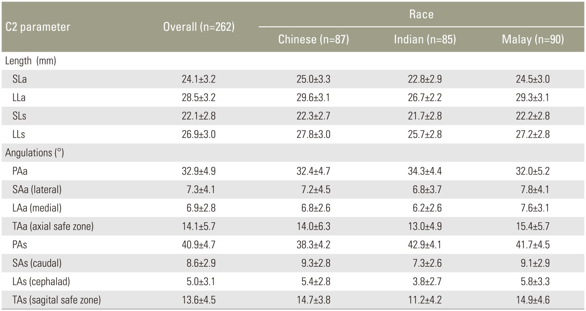
asj-11-181-i003.jpg

Values are presented as mean±standard deviation.

SLa, shortest length in axial plane; LLa, longest length in axial plane; SLs, shortest length in sagittal plane; LLs, longest length in sagittal plane; PAa, pedicle axis in the axial plane; SAa, angle by shortest length trajectory in axial plane; LAa, angle by longest length trajectory in axial plane; TAa, the safe zone in the axial plane; PAs, pedicle axis in the sagittal plane; SAs, angle by shortest length trajectory in sagittal plane; LAs, angle by longest length trajectory in sagittal plane; TAs, the safe zone in the sagittal plane.

Table 4

Summary of the related literatures for C1 lateral mass and the current study

asj-11-181-i004.jpg

NA, not available; CT, computed tomography; M, male; F, femalel; Lt., left; Rt., right; S, shortest; L, longest.

a)Fixed by author; b)In relation to horizon.

Table 5

Summary of the related literatures for C2 pedicle and the current study

asj-11-181-i005.jpg

CT, computed tomography; NA, not available; Lt., left; Rt., right; S, shortest; L, longest; PAa, pedicle axis in the axial plane; PAs, pedicle axis in the sagittal plane.

a)Fixed by author.

TOOLS
Share :
Facebook Twitter Linked In Google+ Line it
METRICS Graph View
  • 5 Crossref
  • 7 Scopus
  • 6,016 View
  • 99 Download
Related articles in ASJ


ABOUT
ARTICLE CATEGORY

Browse all articles >

BROWSE ARTICLES
EDITORIAL POLICY
FOR CONTRIBUTORS
Editorial Office
Department of Orthopedic Surgery, Asan Medical Center, University of Ulsan College of Medicine
88, Olympic-ro 43-gil, Songpa-gu, Seoul 05505, Korea
Tel: +82-2-3010-3530    Fax: +82-2-3010-8555    E-mail: asianspinejournal@gmail.com                
Korean Society of Spine Surgery
27, Dongguk-ro, Ilsandong-gu, Goyang-si 10326, Korea
Tel: +82-31-966-3413    Fax: +82-2-831-3414    E-mail: office@spine.or.kr                

Copyright © 2024 by Korean Society of Spine Surgery.

Developed in M2PI

Close layer
prev next