Feasibility of a novel augmented reality overlay for cervical screw placement in phantom spine models
Article information

Abstract
Study Design
Feasibility study.
Purpose
A phantom model was used to evaluate the accuracy of a novel augmented reality (AR) system for cervical screw placement.
Overview of Literature
The use of navigation systems is becoming increasingly common in spine procedures. However, numerous factors limit the feasibility of regular and widespread use of navigation tools during spine surgery. AR is a new technology that has already demonstrated utility as a navigation tool during spine surgery. However, advancements in AR technology are needed to increase its adoption by the medical community.
Methods
AR technology that uses a fiducial-less registration system was tested in a preclinical cervical spine phantom model study for accuracy during spinal screw placement. A three-dimensional reconstruction of the spine along with trajectory lines was superimposed onto the phantom model using an AR headset. Participants used the AR system to guide screw placement, and post-instrumentation scans were compared for accuracy assessment.
Results
Twelve cervical screws were placed under AR guidance. All screws were placed in an acceptable anatomic position. The average distance error for the insertion point was 2.73±0.55 mm, whereas that for the endpoint was 2.71±0.69 mm. The average trajectory angle error for all insertions was 2.69°±0.59°.
Conclusions
This feasibility study describes a novel registration approach that superimposes spinal anatomy and trajectories onto the surgeon’s real-world view of the spine. These results demonstrate reasonable accuracy in the preclinical model. The results of this study demonstrate that this technology can assist with accurate screw placement. Further investigation using cadaveric and clinical models is warranted.
Introduction
Spinal anatomy presents surgeons with unique challenges, making image guidance technologies an attractive option for enhancing procedural safety and accuracy. The standard practice of spine surgery relies on three-dimensional (3D) positioning using intraoperative fluoroscopy [1,2]. Despite the well-established use of fluoroscopy, it has several drawbacks. Specifically, it is static, requires expensive radiographic equipment with expertise from a radiology technician, introduces additional medical devices into the surgical field, and adds operating time for image acquisition. In addition, radiation poses a medical risk to patients, surgeons, anesthesiologists, and operating room staff [1,2]. Although advanced real-time navigation systems exist, they also have similar drawbacks of increased operative time, cost, and radiation exposure through further requirement of registration scans via intraoperative computed tomography (CT).
Alternative navigation technologies have rapidly emerged over the past several decades by taking advantage of developments in computer vision and augmented, virtual, and “mixed” reality (AR, VR, and MR, respectively) [3,4]. These platforms aim to provide surgical guidance for various procedures without drawing focus from the surgical field. These platforms also benefit from reduced radiation exposure, fewer distracting elements, real-time and adaptive navigation, and potentially enhanced accuracy [5].
Over the past several years, AR has emerged as a promising technology, gaining considerable traction in neurosurgery and orthopedic surgery [6-8]. Unlike VR, in which views of the real-world environment are lost, AR enables users to experience computer-generated content (i.e., holograms) in the real world by merging virtual data such as three-dimensional (3D) anatomy or virtual tools with the real environment [9,10]. The AR system described in this study uses a rapid, markerless registration process to superimpose the 3D-reconstructed spinal anatomy onto the corresponding physical object (i.e., spinal model) to allow visualization and optimization of screw placement. Thus, this study aimed to evaluate the feasibility of this technology as a potential navigation system in spinal surgery.
On the basis of preliminary data and testing of this AR system, we hypothesized that this system can be used to effectively overlay a 3D representation of the spinal models tested efficiently and accurately that is clinically useful. Thus, this proof-of-concept study was conducted to evaluate the feasibility and preliminary accuracy of a novel AR technology system for the placement of cervical spine pars interarticularis and lateral mass screws.
Materials and Methods
Institutional review board approval was not required for this study as this study does not include patient data.
Specimen preparation and imaging
Two spine models (model 1 and model 2) were used in this study. Model 1 was a sawbone model demonstrating the craniocervical junction with the occiput to C4 incorporated. Model 2 was a sawbone model demonstrating the cervicothoracic spine from C1 to T10. The cervical portion of model 2 was used for testing in this study. The phantom models underwent CT at a slice thickness of 0.5 mm with a 512×512 resolution.
Workflow
The workflow of the AR navigation system is shown in Fig. 1. The process begins with CT of the phantom spine model. The segmentation and trajectory lines were assembled into a 3D model. The model was then made available on the headset, and the user initiated the markerless registration process to overlay the 3D digital model onto the phantom model. Each of these steps is described in more detail below.
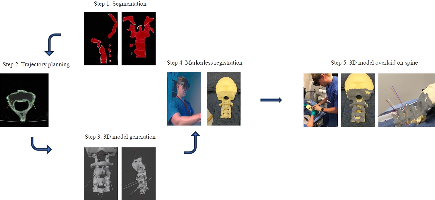
Workflow of the augmented reality (AR) system. Step 1: computed tomography imaging of spine model and segmentation of the vertebrae. Step 2: Trajectory planning. Step 3: Converting segmentation and trajectory annotation into three-dimensional (3D) model. Step 4: User scans phantom while wearing AR headset. Step 5: 3D digital model is overlaid onto the physical model and user can reference trajectory lines when inserting screw.
Segmenting target structures and target trajectories
The phantom spine models were segmented and reconstructed into 3D objects using a 3D slicer. The 3D model included screw insertion trajectories toward various targets that were annotated using a 3D slicer.
A virtual pathway was annotated on the 3D model for each intended screw insertion. Trajectory lines toward the intended targets were annotated on the DICOM (Digital Imaging and Communications in Medicine) file, and subsequently integrated as 3D trajectory lines in the final 3D model (Fig. 2). The trajectories were aimed at placing screws into the bilateral C2 pars interarticularis of model 1 and bilateral C3 lateral masses of model 1 as well as bilateral C3–C6 lateral masses of model 2. After segmentation and annotation, the 3D digital models underwent basic processing to reduce the file size to optimize performance, visual quality, and usability for an AR head-mounted display (HMD).
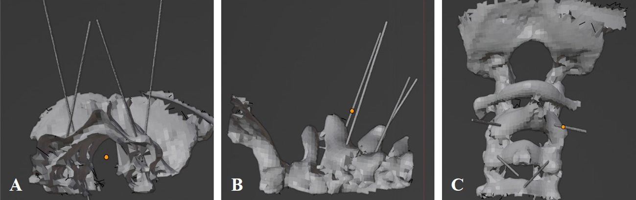
(A–C) Multiple views of the reconstructed three-dimensional (3D) digital spine model with preplanned trajectories. The spine was segmented from the computed tomography scan and annotated with predetermined trajectory lines. Once complete, the segmentation and annotations are converted into a 3D model which is then used for registration to the physical model.
Technology platform
The AR software application was developed by Hoth Intelligence (Philadelphia, PA, USA) and operates on a Microsoft HoloLens 2 HMD (Microsoft Corp., Redmond, WA, USA). The HMD is an optical see-through AR display that superimposes virtual content onto the surrounding “real world.” For this study, the technology platform allows the user to register and superimpose the 3D model (i.e., reconstructed 3D spine model+trajectory lines) onto the phantom spine models. This allows the user to visualize the predetermined screw path directly overlaid onto the model (Fig. 3). The system uses an ultrafast, markerless registration process that allows a user to accurately register preoperative patient imaging for quick navigation in any clinical setting. (1) The registration system operates entirely out of the Microsoft Hololens 2, an untethered 1.2 lb headset wirelessly connected to the Hoth Intelligence cloud data server. (2) Registration does not require fiducial information. The user simply looks down at the spinal vertebra, and the 3D digital model is overlaid onto the physical model. (3) While wearing the HMD, the user scans the spine using various sensors on the Microsoft HoloLens 2. (4) Various sensor streams were integrated and merged to create a modified point cloud of the phantom spine. This serves as input data for the alignment and orientation algorithms used to align the 3D model reconstructed from CT with the sensor data. Feature extraction, pose estimation, and point cloud alignment were performed on the two objects—the 3D digital spine model reconstructed from CT and the HoloLens sensor rendering of the physical spine model—to merge the two objects. Once merged, the realigned digital model is displayed overlaid onto the physical phantom. (5) After registration is complete, users can see the digital model overlaid onto the spine, freely move around the phantom to visualize the model and trajectories from different viewpoints, and proceed with screw insertion by referencing the trajectories (Fig. 3).
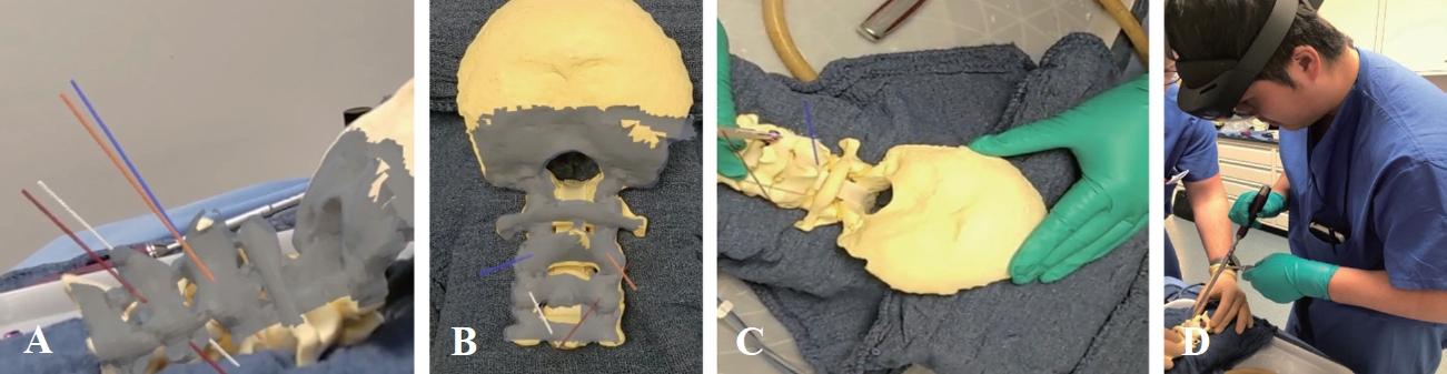
Users view the augmented reality (AR) headset displaying three-dimensional digital model overlaid onto physical spine model. (A–C) Multiple views of the reconstructed vertebrae and trajectory lines overlaid onto the spine model. (D) While wearing the AR headset, the user sees the insertion point and insertion path and can align tools with the trajectory lines while performing steps for screw insertion.
Screw insertion
The study participants were two senior neurosurgery residents (one postgraduate year [PGY]-6 and one PGY-7 resident, both have completed over 500 spine cases in residency) under the Department of Neurosurgery at the University of Maryland Medical Center. Each participant inserted six screws independently for this study, and a total of 12 screws were inserted. After the 3D models were registered to the phantom spine model, while wearing the headset, the surgeon placed screws into the spine at various anatomic locations (Table 1). The surgeon relied on the overlaid trajectory lines to determine the starting insertion point and the path of the insertion. The endpoint of the trajectory line was set such that the distance from the insertion point to the endpoint was identical to the length of the inserted screw. Pilot holes were drilled using a 2-mm cutting burr in a Stryker automatic electric drill. Screw paths were drilled with a 12-mm hand drill. Screw paths were then tapped using a 3.0-mm tap. Bilateral 3.3.5×16 mm C2 pars interarticularis screws and bilateral 3.5×12 mm C3 lateral mass screws were placed in model 1. The same steps were followed for the instrumentation in model 2, in which bilateral C3–C6 lateral mass screws were placed in the standard fashion.
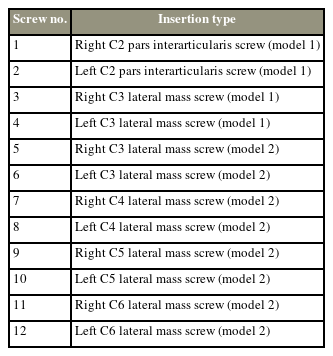
Summary of screw insertions performed
Registration accuracy
After the insertions were complete, the phantom spine underwent CT again. To measure the target registration error and trajectory angle error, the preoperative planned CT scans containing annotated screw trajectories were merged with the postinsertion CT scans containing the inserted screws. Two target points—insertion point and endpoint—were identified and measured to calculate targeting accuracy. The x, y, and z coordinates of the insertion and endpoints of both the preplanned trajectories (preinsertion CT) and the inserted screw (postinsertion CT) were obtained from the scans, and the distance between the corresponding points was measured. To measure the trajectory angle error, the 3D models of the fused preinsertion and postinsertion scans were generated and analyzed using 3D slicer modeling software. The angle between the preplanned trajectory and the inserted screws was measured (Fig. 4).
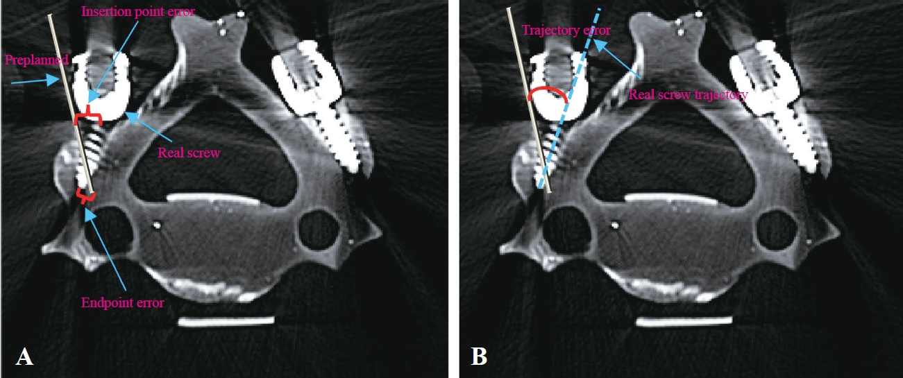
Pre-insertion and post insertion computed tomography images were fused. (A) The insertion point and endpoint distance error were measured as the Euclidian distance between the corresponding points of the preplanned trajectory and real screw. Multiple views of the reconstructed three-dimensional digital spine model with preplanned trajectories. (B) The trajectory angle error was measured as the angular difference between the preplanned trajectory and the physical screw path.
Results
Registration time
The 3D model was registered onto the phantom for each screw insertion, for a total of 12 registrations. The 3D model was downloaded onto the headset, and the registration process was initiated to overlay the digital model onto the phantom. Because of the fast download, the time for 3D model download is negligible and not included in the registration time measurement. Therefore, the registration time was defined as the time from the start of the registration workflow to the successful visualization of the digital model overlaid onto the phantom. The steps include scanning the phantom model with the headset, running alignment algorithms, and rendering the transformed 3D model overlaid onto the spine models. The average registration time across all registrations was 17.4±2.1 seconds.
Registration accuracy
All 12 screws were successfully inserted (Fig. 5). The distance error between the preplanned pathways and the inserted screws was measured for both the insertion point and endpoint. The average distance error for the insertion point was 2.73±0.55 mm, whereas the distance error for the endpoint was 2.71±0.69 mm. The average trajectory angle error for all insertions—defined as the angular difference between the preplanned trajectory and the physical screw path—was 2.69°±0.59°. A summary of the results of all insertions is displayed in Table 2.
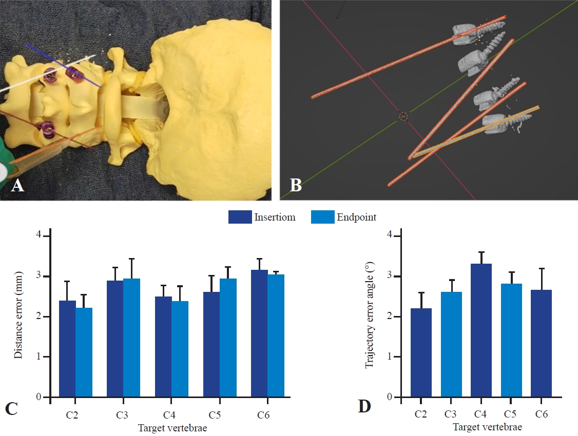
(A) Users view through the headset displaying trajectory lines and screws that were inserted along the overlaid trajectory lines. (B) Three-dimensional representation trajectory lines and inserted screws of the merged pre-insertion and post insertion computed tomography images used to estimate distance and trajectory angle error. (C) Average distance error of the insertion point and endpoints. (D) Average trajectory angle error. All results are reported as mean±standard error of mean.
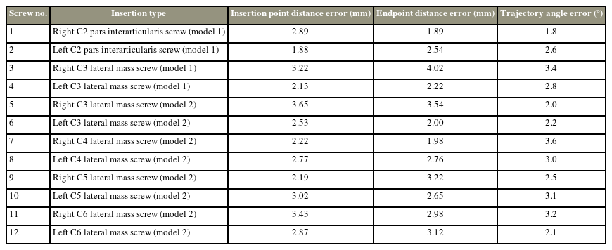
Accuracy results of all screw insertions
A notable advantage of AR is the seamless interaction and visualization of 3D models. As such, the phantom spine with screws was reconstructed from the postinsertion CT and studied through the HMD (Fig. 6). Once downloaded onto the headsets, users could use the AR display to visualize and interact with the 3D model, studying their screw insertion performance from different viewpoints (Fig. 6).
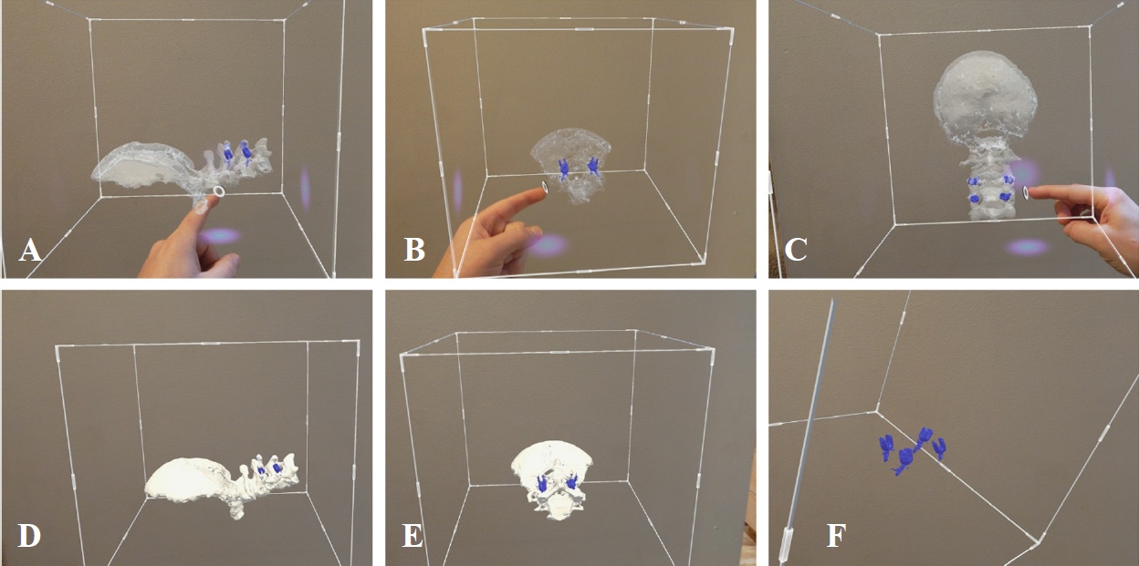
(A–F) Multiple views of the users’ view the headset visualizing the three-dimensional (3D) reconstruction of the post-insertion computed tomography scan. Augmented reality overlays digital images onto the real-world view. Users can study and manipulate 3D reconstructions of the bony anatomy as well as the inserted screws.
Discussion
This proof-of-concept study evaluates the feasibility and baseline accuracy of a novel AR system that uses markerless registration for the guidance of cervical screw placement in two spine models. While further optimization is warranted, the presented results support the hypothesis that the AR technology described herein can be used for cervical screw placement. In this phantom model experiment, the average insertion point distance error was 2.73±0.55 mm, the average endpoint distance error was 2.71±0.69 mm, and the average trajectory angle error was 2.69°±0.59°. In addition, the registration process is relatively fast, demonstrating an average time of 17.4 seconds to overlay the 3D digital model with the physical phantom.
AR systems for intraoperative guidance during spine surgeries have tremendously improved. Previous studies have demonstrated the unique advantages of ARbased image guidance systems [3,11,12]. However, current intraoperative navigation and AR systems have notable limitations such as size, cost, and requirement of intraoperative scanning (i.e., intraoperative CT, magnetic resonance imaging [MRI], and/or fluoroscopy) for registration. In addition, existing AR surgical guidance platforms typically rely on the registration of markers placed within the surgical field. Registration using these markers usually requires placement of a small yet potentially invasive marker on or in the patient and more time in the operating room and is associated with increased obstacles to the surgical field, increased cost, and further challenges faced if reregistration is required during a procedure [13,14]. The platform evaluated here demonstrates novelty because it does not require any fiducial markers but uses the natural curvature and unique anatomical points on the patient’s exposed anatomy to generate a spatial map. In addition, as the data indicated, the speed of the system is evident with the entire registration process occurring on a timescale of seconds as opposed to minutes in typical navigation. The ability to use preoperative spinal CT scans for registration may circumvent the need for intraoperative CT when using navigation. This could reduce time, cost, and radiation exposure.
Participants could successfully visualize the 3D reconstruction of the phantom and preplanned screw trajectories overlaid onto their real-world view of the physical phantom model. Accordingly, participants could align their surgical tools with preplanned trajectories and use these trajectories during spinal hardware insertion. Thus, some inaccuracies were noted in the system, which may be attributed to various factors. First, without instrument tracking, the participants relied on hand–eye coordination and depth perception to align physical screws with the virtual trajectory, which can be challenging and lead to imprecision. In addition, this technology, like other AR technologies, is subject to image drift, which means that the registered 3D model may shift. Although the technology presented herein is designed to minimize any drift, shifting may still occur, causing a minor shift in the location of the trajectory lines. In addition to these technical limitations, this study has considerable design limitations. This is a proof-of-concept and feasibility study; thus, future studies are expected to explore the expanded use of this technology. CT was the only imaging modality used in this study; however, follow-up work aims to explore the registration of MRI and fused MRI and CT registration. This approach is feasible because the registration process of this system is imaging modality agnostic. The combined visualization of bony and soft tissue anatomy is an exciting potential future use case and could considerably increase the level of accuracy and granularity in the current state of navigated spinal surgery. In addition, the current system does not integrate instrument tracking. Currently, the system displays the trajectory only; however, the ability to align surgical tools and screws more precisely with the trajectory and the ability to more confidently determine when proper depth is reached are plausible next steps of experimentation. The addition of the ability to navigate spinal hardware in real time with this platform will potentially increase the accuracy and enable control during screw insertion.
Although the size, speed, and accuracy of the system are highly encouraging, some issues must be considered in practical applications and clinical practice. Notably, this study was conducted in phantom models rather than in human tissues. Despite the fidelity of the models, the presence of soft tissue such as fat, muscle, or blood in the surgical field may be a confounding variable. While these variables have been considered during technology development, testing in models similar to actual patient conditions (i.e., tissue phantom models and cadavers) with traditional spine exposure is warranted. In addition, this technology was only applied to the cervical lateral mass and pars interarticularis screws. Further studies evaluating the feasibility of thoracic and lumbar pedicle screw placement are warranted. Moreover, this technology requires exposure of the spine. Therefore, as the technology currently stands, it is limited to open spine surgery and does not yet have practical applications for minimally invasive approaches. The study was also limited by the small number of surgeon participants, small number of screw insertions, and use of physiological spine models. It will be critical to evaluate the system’s accuracy and usability in greater numbers across various surgeons with varied skill and experience levels as well as pathologic spine models to better understand its clinical relevance.
Conclusions
This study demonstrates the use of a novel AR registration system for registering 3D reconstructions of the cervical vertebra to the physical spine. Given the novelty of the system, its accuracy and usability were first evaluated in a phantom spine model. Despite the limitations of this study, these preliminary data are promising and substantiate further testing of the system, further highlighting the potential for clinical application in the future.
Notes
Conflict of Interest
No potential conflict of interest relevant to this article was reported.
Author Contributions
Conceptualization: JO, BS, NH, AS, AT, KK, GS, SL, CS. Data curation: JO, BS, NH, AS, AT, KK. Formal analysis: JO, AT, KK, GS, SL, CS. Methodology: JO, BS, NH, AS, AT, GS, SL, CS. Writing: JO, BS, AT, GS, SL, CS. Supervision: GS, SL, CS. Final approval of the manuscript: all authors.