


Introduction
Posterior cervical spine stabilization and fusion is frequently performed to address various cervical pathologies [1]. In long cervical fixation constructs, the necessity of establishing a secure anchor at the C7 vertebra cannot be underestimated [2]. Current posterior subaxial cervical spine stabilization systems primarily employ a screw–rod design [3]. These biomechanically sturdy designs are associated with higher fusion rates, early mobilization, faster rehabilitation, and ultimately better clinical outcomes [4,5]. Although several posterior cervical decompression and fusion procedures are performed annually, dispute persists regarding the most effective surgical approach, particularly with respect to the selection of the upper and lower instrumented levels in a multilevel construct. Most studies to date have focused primarily on the controversies around the technique and level of the lower instrumented body. On the contrary, few studies have analyzed the effect of terminating the construct proximally at the C2 vertebra instead of at C3 [6,7]. Extending the construct proximally to the C2 vertebra allows a tri-column stabilizer effect of the construct. However, this is associated with longer surgical duration, risk of iatrogenic vascular injury, and greater tissue handling [7]. One of the most common anchors used for posterior fixation at the C7 vertebra is the lateral mass screw (LMS) fixation. The most significant benefit is that it offers reliable fixation and has a low rate of neurovascular damage [8–10]. Cervical pedicle screw fixation, although precarious and challenging from C3 to C6 [11], is practically possible at the C7 vertebra because of its homology to the thoracic vertebrae and favorable relationship with the vertebral artery [12]. Furthermore, because the C7 vertebra is frequently the most caudal point of fixation in multilevel structures and the location of greatest stress concentration, concerns about appropriate screw placement are frequently centered on the C7 vertebra [13]. As regards multilevel posterior cervical fixation construct, groups have polar views: one advocating LMS at the C7 vertebra caudally primarily because of technical ease and relatively lower incidence of vascular and neurologic injury, and the other favoring transpedicular screws (TPS) at the C7 vertebra because of the higher pullout strength of the screw [13]. Over the years, studies have discussed the advantages and drawbacks of LMS and TPS at the C7 vertebra caudally, along with the preference for various fixation techniques based on patient demographics [12–15]. However, studies comparing the biomechanics of different multilevel posterior cervical fixation constructs are limited. In this finite element (FE) analysis (FEA), we aimed to compare the biomechanical parameters of commonly utilized multilevel posterior cervical fixation constructs incorporating the C7 vertebra using two techniques: LMS fixation versus TPS fixation. This FEA study can be a reference for further research and clinical adaptation in the field.
Materials and Methods
1. Generation and validation of the finite element model
Computed tomography (CT) scan of a healthy 35-year-old man was used to construct a three-dimensional (3D) FE model of a typical cervical segment ranging from the skull base to the T1 vertebra [16,17] (Fig. 1). Mimics ver. 10.01 (Materialise, Leuven, Belgium) was used for importing the scans and recreating the vertebra levels. The geometric model was then transferred to Geomagic Design ver. X16.0 (Geomagic, Durham, NC, USA) for refining procedure. Using HyperMesh software (Altair Engineering, Troy, MI, USA), the intervertebral disc, ligaments, and vertebral bone meshing were created and loaded into ANSYS ver. 18.2. software (ANSYS Inc., Southfield, MI, USA). ANSYS was utilized to define the element type, material property, and loading condition. The C2–T1 cervical vertebral bodies, posterior bony elements, intervertebral disc consisting of the annulus fibrosus and nucleus pulposus, inferior and superior vertebral endplates, and ligaments were all incorporated in the cervical spine FE model. The literature-recommended intervertebral disc height was maintained [18–22]. The vertebrae, discs, and endplates were all assigned the element property of first-order solid tetrahedral elements.
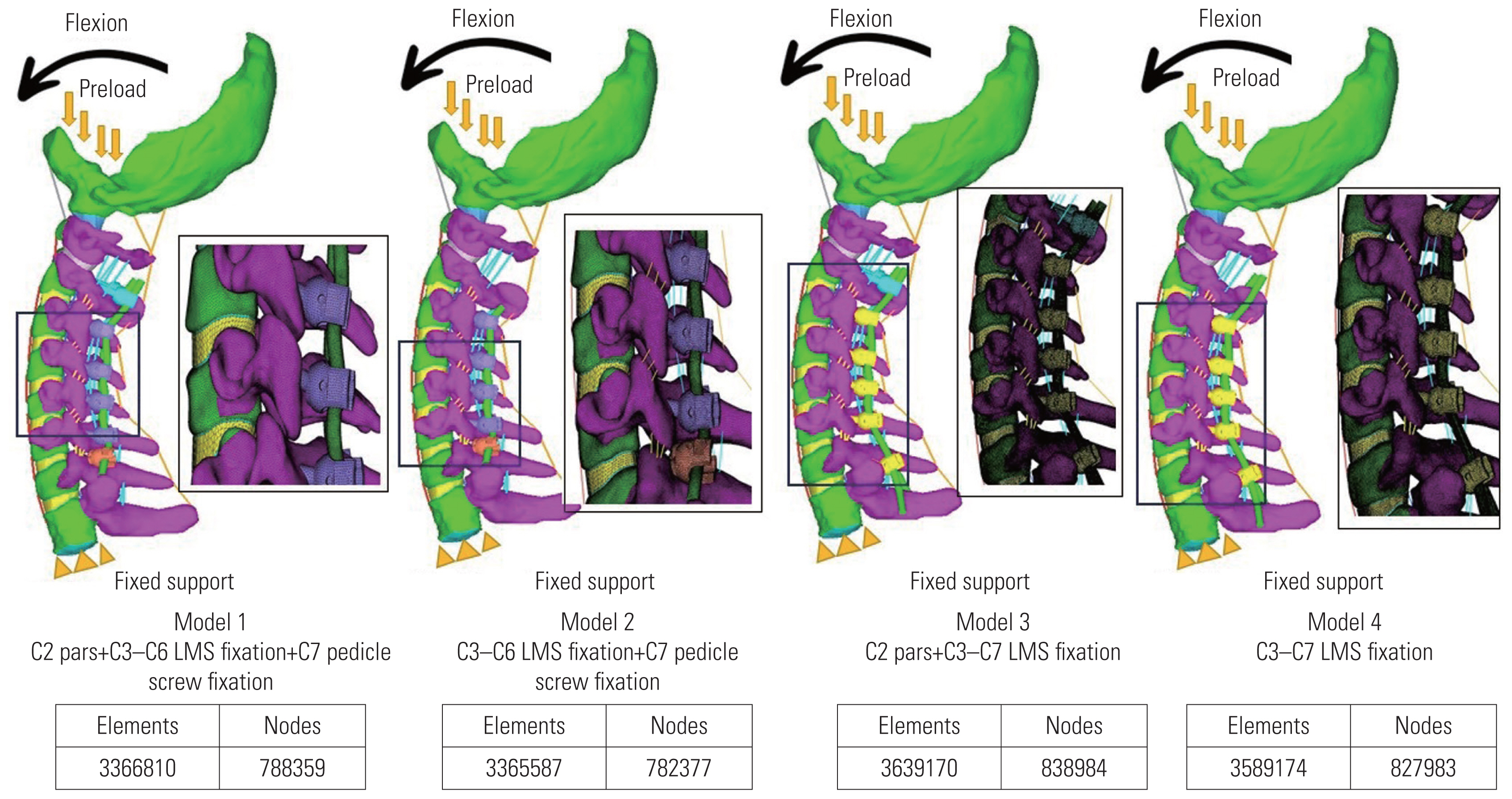
The model assessed the anterior longitudinal ligament, capsular ligament, posterior longitudinal ligament, interspinous ligament, and ligamentum flavum [18–22]. The ligaments’ geometry was recreated using literature data [18–23]. Two-node tension link elements were used to simulate these ligaments. The material properties of the FE model are presented in Table 1 [23–26]. After performing the convergence test, the ideal size for the tetrahedral element was determined to be 0.5 mm [24]. For our FE model, the convergence test’s accuracy was 3% [27]. At the superior endplate of the C2 vertebra, a preload of 50 N of compressive force was applied to replicate the head weight, along with moment variations [16,27]. The inferior endplate of the C7 level motion was fully constrained in each loading protocol (Fig. 2). The dimensions of the screws are provided in Fig. 3.
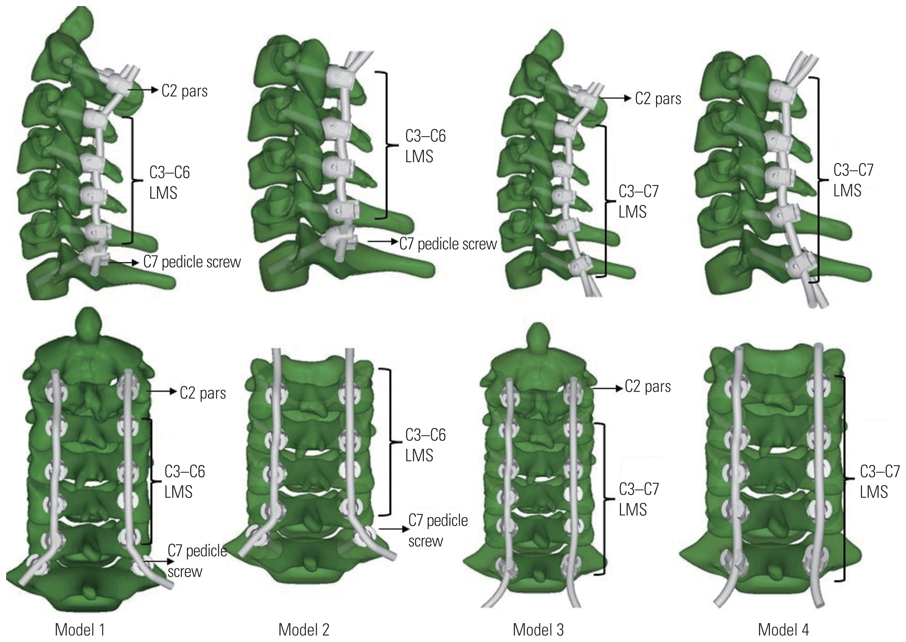
Four 3D FE models of multilevel posterior cervical fixation ranging from the skull base to the T1 vertebra were tested and compared by FE analysis in various permutations and combinations (Fig. 2): model 1: C2 pars C3–C6 LMS and C7 pedicle screws; model 2: C3–C6 LMS and C7 pedicle screws; model 3: C2 pars and C3–C7 LMS; and model 4: C3–C7 LMS.
In all models, laminectomy was not performed.
Principles of screw fixation and screw trajectory in posterior cervical instrumentation were followed (Fig. 4) [17]: (1) LMS involve only the posterior column from C3 to C7. (2) Pars screws involved only the posterior column at C2. (3) Pedicle screws involved all three columns at C7. (4) LMS were directed laterally and cranially. (5) Pars screws were directed medially and cranially. (6) Pedicle screws were directed medially and neutrally.
2. Material properties and dimensions
The materials were titanium alloy LMS, pedicle screw, pars screws, and connecting rods. The dimensions of screws used were represented in Fig. 3: (1) lateral mass and C2 pars screws: 3.5 mm in diameter and 12–18 mm in length; (2) C7 pedicle screw: 4 mm in diameter and 24–30 mm in length; and (3) T1 pedicle screw: 4 mm in diameter and 30–40 mm in length. The dimensions of the rods used were 3.2 mm in diameter.
3. Loading conditions
For each model, at the superior endplate of the C2 vertebra, a preload of 50 N of compressive force was applied to replicate the head weight along with moment variations [16,27]. In each loading protocol, the inferior endplate of C7 level motion was fully constrained. The same boundary and loading conditions were adapted for all four models.
4. Parameters to be recorded
The following parameters were recorded for each model: (1) maximum moment at failure, (2) maximum angulation at failure, (3) maximum stress at failure, (4) point of failure, (5) intervertebral disc stress, and (6) influence of adding a C2 pars screw to the multilevel construct.
5. Ethics clearance
Informed written consent was obtained from the volunteer before using CT scans to generate the cervical spine 3D finite element models used in the study. This study did not involve research conducted on human volunteers/animal specimens. No confidential data were collected/published during/after the research from any human participants. Because of the aforementioned reasons, the study was exempted from the need for clearance from the Institutional Ethical Committee.
Results
The intact 3D FE model consisting of the skull base–T1 vertebra was successfully reconstructed through CT and digital image processing utilizing Mimics ver. 10.01 (Materialise), Geomagic Design ver. X16.0 (Geomagic), HyperMesh (Altair Engineering), and ANSYS ver. 18.2. (ANSYS Inc.).
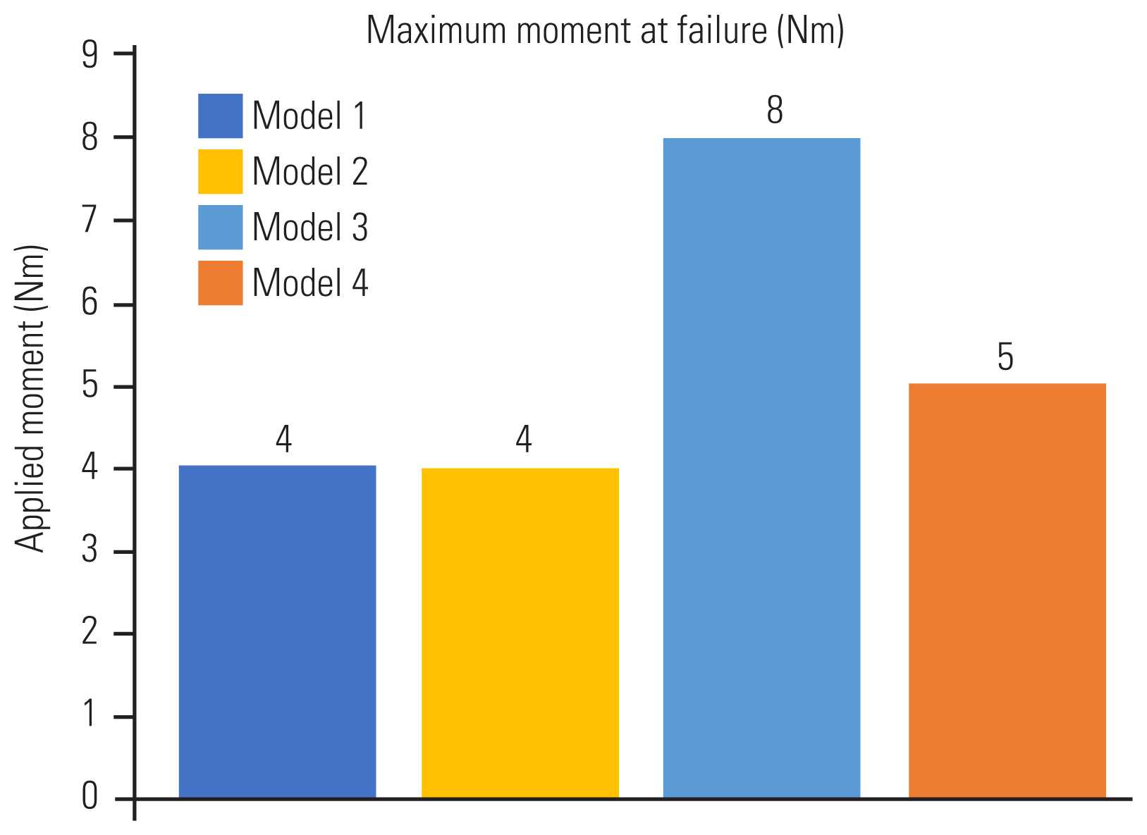
1. Maximum moment at failure
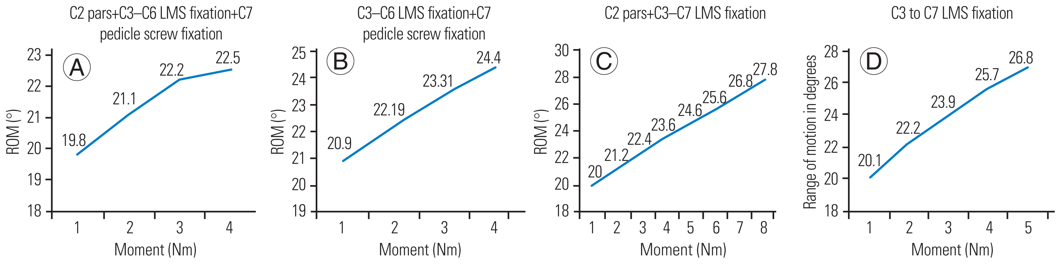
For all models, the load applied was 50 N of compressive force, along with moment variations. The maximum moment generated in the flexion motion at the time of failure was the highest for model 3, i.e., construct with C2 pars + C3–C7 LMS, followed by model 4, i.e., construct with C3–C7 LMS (8 Nm and 5 Nm, respectively). Compared with models 3 and 4, the two models with TPS fixation at C7, i.e., models 1 and 2, elicited a lower maximum moment generated during failure (4 Nm in both models 1 and 2) (Fig. 5).
2. Maximum angulation at failure
In model 1, the maximum moment generated at failure and the maximum angulation in flexion permitted were 4 Nm and 22.5°, respectively. In model 2, the maximum moment generated and the maximum angulation permitted were 4 Nm and 24.4°, respectively. In model 3, the maximum moment generated and the maximum angulation were 8 Nm and 27.8° in flexion, respectively. In model 4, the maximum moment generated and the maximum angulation permitted were 5 Nm and 26.8°, respectively (Fig. 6).
3. Maximum stress at failure
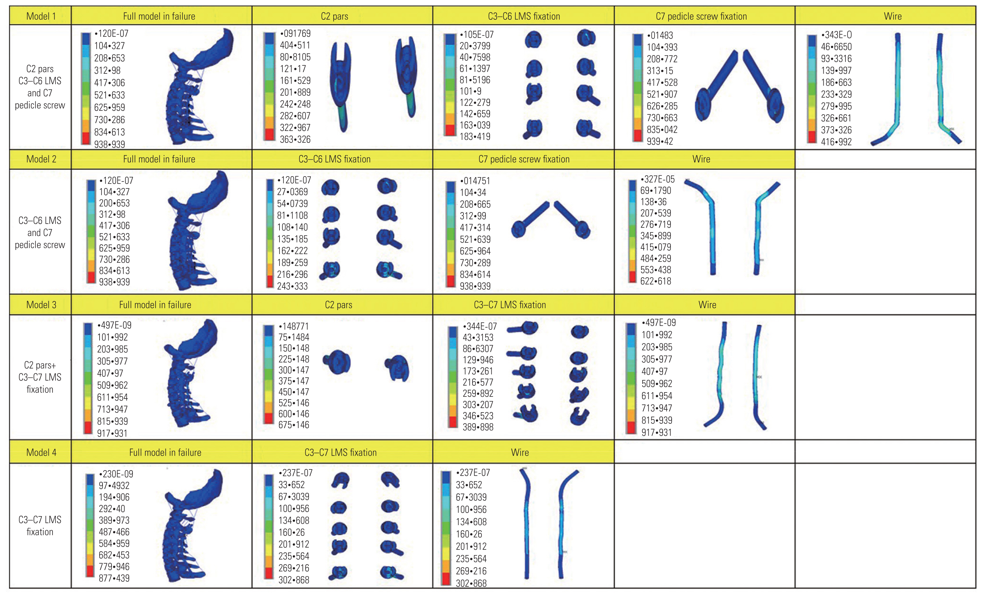
Model 1 tolerated the maximum von Mises stress, whereas model 3 could withstand the least von Mises stress at failure. The maximum von Mises stress tolerated by models 1, 2, 3, and 4 were 939.42 MPa, 938.9 MPa, 917.9 MPa, and 877.4 MPa, respectively.
In model 1, the maximum von Mises stress at the maximum moment at failure at C2 pars screw, C3 LMS, C4 LMS, C5 LMS, C6 LMS, C7 TPS, and rods were 363.3 MPa, 54.1 MPa, 32.8 MPa, 183.4 MPa, 84 MPa, 939.4 MPa, and 419.9 MPa, respectively. In model 2, the maximum von Mises stress at the maximum moment at failure at C3 LMS, C4 LMS, C5 LMS, C6 LMS, C7 TPS, and rods were 243.3 MPa, 153.7 MPa, 174.7 MPa, 78.3 MPa, 938.9 MPa, and 622.6 MPa, respectively. In model 3, the maximum von Mises stress at the maximum moment at failure at the C2 pars screw, C3 LMS, C4 LMS, C5 LMS, C6 LMS, C7 LMS, and rods were 675.1 MPa, 75.9 MPa, 215.5 MPa, 389.8 MPa, 147.7 MPa, 299.9 MPa, and 917.9 MPa, respectively. In model 4, the maximum von Mises stress at the maximum moment at failure at C3 LMS, C4 LMS, C5 LMS, C6 LMS, C7 LMS, and rods were 302.8 MPa, 180.6 MPa, 264.5 MPa, 90.9 MPa, 201.8 MPa, and 877.4 MPa, respectively. The maximum stress generated at the implants during the maximum moment at the time of failure is presented in Table 2.
4. Point of failure
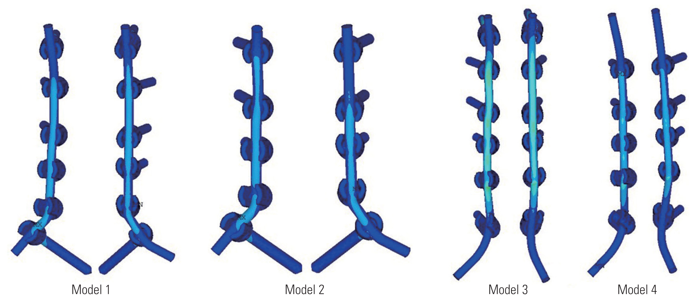
Models 1 and 2 failed at the C7 TPS at the maximum moment of 4 Nm. Model 3 failed at the C4–C5 rod at the maximum moment of 8 Nm. Model 4 failed at the rod cranially at the C3–C4 level at the maximum moment of 5 Nm (Table 3).
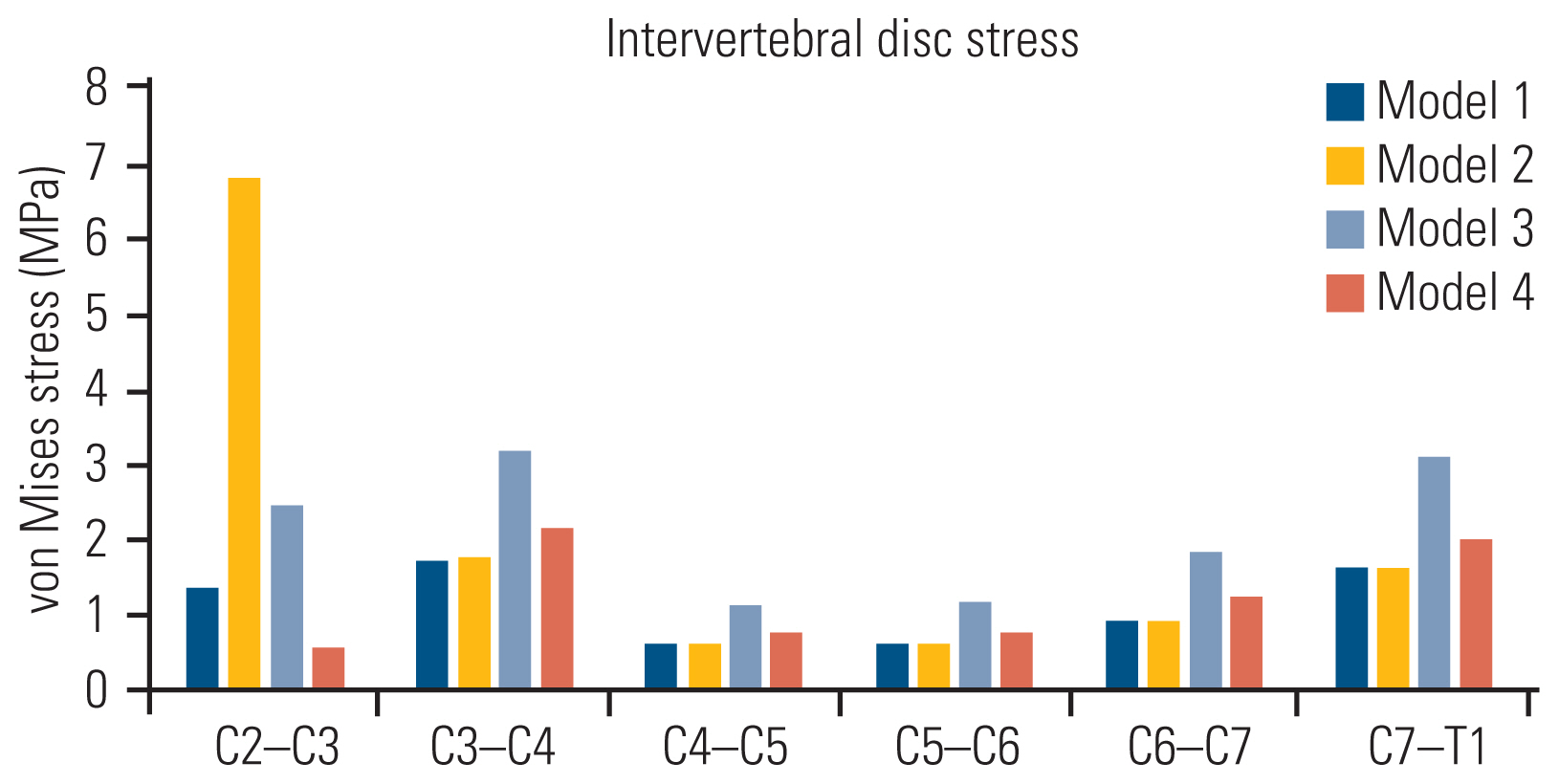
5. Intervertebral disc stress
The intervertebral disc stress (von Mises stress in MPa) at the maximum moment of failure in flexion is provided in Table 4 and Fig. 7. Models 1 and 2 show lesser von Mises stress at C6–C7 and C7–T1 (0.93 MPa and 1.64 MPa, respectively) than model 3 (1.87 MPa and 3.13 MPa, respectively) and model 4 (1.25 MPa and 2.03 MPa, respectively).
6. Influence of adding a C2 pars screw to the multilevel construct
For both models 1 and 3 where C2 fixation was performed, lower von Mises stress was recorded at the C2–C3 intervertebral disc level (Table 4, Fig. 7). Von Mises stress of 1.39 MPa and 2.46 MPa were recorded at C2–C3 in models 1 and 3, respectively. The models as seen on failure, point of failure, trajectory of instruments, and the stress of each component are summarized in the contour plot in Fig. 8.
Discussion
To our knowledge, this is the first study to include FE models to study multilevel posterior cervical fixation constructs and evaluate the biomechanical properties of LMS and TPS at the caudal level, i.e., C7. Existing works include cadaveric and clinical studies comparing the clinicoradiological outcomes of LMS versus TPS at the C7 vertebra [28]. However, these studies have primarily employed monosegmental or bisegmental fixation models. We hope to confirm the validity of existing data with this FE study and use this study as groundwork for future cervical spine FE studies.
The C7 vertebra has a unique anatomy compared with other subaxial vertebrae in terms of its relationship to the vertebral artery and its junctional location in the spinal column [11]. For any multilevel fixation construct, careful planning for the screw fixation at the C7 vertebra is of utmost importance [29]. The distinctive morphology of the lateral masses at the C7 vertebra and its inconsistent relationship to the vertebral artery require careful preoperative planning with appropriate investigative modalities before C7 fixation [30]. Although LMS fixation remains the gold standard for C3–C6 fixation, the ideal choice of the fixation technique at the C7 vertebra in a multilevel posterior cervical fixation construct remains debatable. LMS and TPS fixations are the two most popular methods of stabilizing the cervical spine. With the combined usage of autogenous bone grafting, LMS fixation in cervical trauma led to fusion rates >95% [31,32]. Because of a smaller lateral mass at the C7 vertebra, LMS fixation at this level often achieves inadequate purchase, thereby requiring TPS fixation of the lower cervical spine and upper thoracic vertebrae. In the past, TPS have greater fixation stability [33–35]. This study was conducted to evaluate differences in the biomechanics of multilevel posterior cervical fixation constructs, ending caudally at the C7 vertebra with LMS and TPS in response to motion and stress.
The maximum moment generated at failure was lower for long subaxial cervical constructs terminating with TPS than those terminating with LMS. The reason was that TPS have a longer lever arm, spanning all three vertebral columns, whereas the LMS anchors only to the posterior column. This in turn provided a stiffer mechanics to the subaxial construct.
The maximum angulation of the cervicothoracic spinal model in flexion was greater for constructs with C7 LMS than those with C7 TPS. This again is attributed to the tricolumnar purchase of TPS fixation compared with LMS fixation that controls the posterior vertebral column only. These findings are in accordance with the results of Duan et al. [36].
On loading the models with compressive force in flexion motion, the accumulation of von Mises stress over the implants was greater for LMS models than for TPS models. Along with this, the variability in the von Mises stress at each intervertebral disc space was greater for models terminating caudally with LMS than those with TPS. In the analysis of the von Mises stress variability at each intervertebral disc, the concentration of von Mises stress at the implants was considered a measurement of the potential for greater risk of fixation device fracture. In this study, the von Mises stress at C6–C7 and C7–T1 intervertebral discs were lower for TPS than for LMS fixation. This indicated the higher stress shielding nature of the TPS at the C7 vertebra and adjacent disc levels.
For models 1 and 3 where the construct was extending up to C2 fixation proximally, the von Mises stress at the C2–C3 level was lower than that at models 2 and 4 where C2 was unconstrained. The von Mises stress at C2–C3 and C3–C4 was the lowest for model 1 where C2 pars screw and C7 TPS were used. Adding a C2 pars screw to the posterior cervical construct increased the constraint of the system. It also ensured lesser variability of the von Mises stresses across various levels, thereby reducing the risk of implant fracture and related complications.
The salient features of this study are as follows: (1) This study is the first to include an FE model to evaluate the biomechanics of multilevel posterior cervical fixation with LMS and TPS at the C7 vertebra. (2) Existing literature includes cadaveric and clinical studies comparing the clinicoradiological outcomes of the two fixation modalities. However, these studies have employed monosegmental/bisegmental fixation models. Moreover, clinical studies require a lengthy follow-up. Many patients in these settings are lost by attrition during follow-up.
This study has a few limitations. First, only a one-time fixed compressive force was loaded with flexion angulation. The model was not tested with repetitive stress loading or in extension/side-bending motions. We hope to use this study as the groundwork for more intricate FE studies in the future. Second, the bone–screw contact was modeled as bonded (homogenous entity), ignoring any potential micromotions. The calculated outcomes are solely dependent on simulated conditions and should only be evaluated for reference.
Considering the aforementioned constraints, this study can be a foundation for future research aimed at the dynamic analysis of the subaxial cervical spine construct via multidirectional movements under varied degrees of loading conditions. This study unequivocally validates existing data on multilevel subaxial cervical spine models.
Conclusions
Ending a multilevel cervical construct with TPS fixation rather than LMS fixation at the C7 vertebra provides a stiff and more constrained construct system, with higher stress endurance to compressive force. The constraint and durability of the construct can be further enhanced by adding a C2 pars screw in the fixation system. This study using FEA models provides a platform to study and compare the biomechanical properties of various posterior cervical fixation designs and paves the way for more cervical FE studies in the future.