Asian Spine J Search

CLOSE


Asian Spine J > Volume 17(5); 2023 > Article
Lin, Paul, Dhar, Doulgeris, O’Connor, Tsai, and Vrionis: A Review of Finite Element Modeling for Anterior Cervical Discectomy and Fusion

Abstract

The cervical spine poses many complex challenges that require complex solutions. Anterior cervical discectomy and fusion (ACDF) has been one such technique often employed to address such issues. In order to address the problems with ACDF and assess the modifications that have been made to the technique over time, finite element analyses (FEA) have proven to be an effective tool. The variations of cervical spine FEA models that have been produced over the past couple of decades, particularly more recent representations of more complex geometries, have not yet been identified and characterized in any literature. Our objective was to present material property models and cervical spine models for various simulation purposes. The outlining and refinement of the FEA process will yield more reliable outcomes and provide a stable basis for the modeling protocols of the cervical spine.

Introduction

The cervical spine is one of the smallest and most intricate joints in the human body [1]. Cervical disc herniations are a problem caused by repetitive cervical spine loading [2]. The severity of loading needed also decreases as the age of involved patients increases [3]. This is due to a lack of nutrient supply to the intervertebral disc; resulting in natural wear and decreased performance with age, a phenomenon known as cervical spondylosis [4]. If the disc degenerates, the cervical spine’s stability will be compromised, and the intravertebral disc height will change [5]. The decrease in foraminal spacing can result in cervical radiculopathy and the compression of nerves causes great discomfort and reduced quality of life for the affected individual [6].
The first attempts made at addressing this were through the fusion of the adjacent vertebra in a technique known as anterior cervical discectomy and fusion (ACDF) established in the 1950s [7]. The intervertebral disc and osteophytes are removed during this treatment, and the area of the spine is decompressed. Then, to maintain foraminal spacing and to encourage a stable site for osseointegration, an adequately sized cage and bone graft are implanted [8]. Shortly after, plate instrumentation was introduced to help regulate the stresses of the cervical spine. A variety of surgical techniques and hardware have been developed in addition to the standard anterior plating, to improve the biomechanical postoperative state. Some adjunct structures that have been applied include lateral mass and pedicle screw systems, facet replacement devices, and cervical disc replacements for multilevel procedures [9]. For the treatment of cervical disc problems, the golden standard has not yet been discovered [10]. To better meet the needs of the system, more information on the generalities and mechanics of the cervical spine is required. Many techniques have been used to learn more about the cervical spine [11].
The finite element is important for predicting spine mechanics in situations where in vivo and in vitro models prove insufficient. In the determination of internal loads, stresses, and strains in spinal tissue, numerical models have been used [12]. Simulation results from numerical spine models can be employed to gain insight into the inner workings of the cervical spine [13]. Moreover, virtual models can display information previously unobtainable via physical models, such as stress distribution in the intervertebral disc. Gradually, more accurate cervical spine modeling has increased the accuracy of the guidance of spine surgery and the new design of cages. The only notable drawback is that greater computing power is needed. This is controlled by converting models into somewhat less computationally intensive versions. The findings they offer will still be quite accurate if they pass convergence tests and are validated against data that is known to be accurate. Cervical spine modeling has been the subject of multiple reviews of the literature, but there have not been any that contrast cervical spine models with material models. The limitations of the material models and cervical models were not compared and discussed. We will therefore focus on reviewing the material property models and cervical models for potential interest to the surgeons and biomechanical engineers.

Material Models

The behavior of a given material under loading is described by material models. Based on how accurately they depict the kind of material being described, material models are chosen. Different material models may be applicable for the same material since they can yield results that are more consistent in some movements while visibly less accurate in others. However, a standard for which models are most applicable for each anatomical structure has emerged from the use of these models in a wide variety of loading conditions.

1. Vertebrae

The cervical vertebra could be represented by up to three different structural elements. The exterior cortical bone and the interior cancellous, or trabecular, bone can be used to simulate the vertebral body [14]. Some research place greater emphasis on the transverse process, lamina, and spinous process as more central to the results of the study; in that literature, a third body is added for the posterior region to have greater accuracy in the model. The cortical bone and cancellous bone are described in some sources as orthotropic, however, the vertebra is typically approximated with an isotropic elastic model. The posterior body is typically modeled in the same way as the cancellous bone when it is included [15]. The posterior bone is quite consistent across the literature with the exception of Kopperdahl et al. [16] who employed an isotropic, power-law plasticity material model for the diagnosis of bone damage [15,1719].

2. Endplate and facet joints

The vertebral, or bony, endplate and the cartilaginous endplate make up the endplate structure. Typically, an isotropic elastic model is applied to the facet joints [20]. To ensure a smooth passage of forces between the facet joints, Kumaresan et al. [21] devised a simplified facet joint model similar to the fluid-based facet joint model.

3. Intervertebral disc

The nucleus pulposus and the annulus fibrosus (AF) are the two parts of the intervertebral disc. Since the nucleus pulposus is a viscoelastic material, the loading condition affects how it behaves. In addition to the traditional isotropic elastic model, an occasional hyperelastic model may be utilized; some literature even regards the nucleus as a fluid of varying compressibility [22,23]. A single section was successfully modeled in quasi-static conditions by Yang and Kish [24] using a fluid material model with a bulk modulus of 1.720 GPa. However, the nucleus pulposus was modeled using the linear viscoelastic model to recreate the whole cervical spine model [25].
The AF is considered as two parts in literature, a ground substance and several layers of angled fibers. Hill [26] modeled AF ground substance with an isotropic, nonlinear strain-energy function while still preserving the compressibility of quasi-static simulations such as that presented by Storakers [27]. The annulus ground has been represented utilizing an isotropic elastic model, hyperelastic models like the neo-Hookean, the Mooney-Rivlin model, or as a Hill foam [15,17,28].
The annulus was modeled by Cassidy et al. [29] using five layers whose angles changed depending on the radial position. According to Eberlein et al. [30], a nonlinear tension-only fiber model was merged with a novel Hooke hyperelastic base material to create an anisotropic constitutive model.

4. Ligaments

Numerous ligaments with various stress-strain relationships reside in the cervical spine, although their general behavior is constant. As a result, in each analysis, the ligaments in the area are all modeled using the same material model. According to the stress-strain relationship or the force-displacement curve, the ligaments are classified as either a hyperelastic material or a tension-only element [15,17,18,28]. These elements are generally tension only and occasionally include a cross-sectional area [19]. In their investigation of the high rates of ligament deformation, Yoganandan et al. [31] found that viscoelastic effects were more prominent in complete spine models, necessitating the use of a dynamic scaling factor.

5. Muscles

The Hill-type muscle’s passive muscle is the only part that adheres to a conventional material model. A bilinear elastic model with non-linear dampers and a hyperelastic Ogden model with linear viscoelasticity are the two fundamental models for the depiction of the passive muscle. Within the usage of either of these models, no difference exists in material parameters between muscle groups.

6. Spine hardware

Isotropic elastic materials are commonly used to describe surgical devices. Because the standard materials utilized in this method (titanium, cobalt chrome, stainless steel, PEEK) all adhere to the same material model, there is very little variation.

Material Properties

There is great variation in the material properties utilized in FEA for ACDF. The variety in the cadaver specimens used for the development and validation of the original models is the cause of many of these variations. Tables 13 list all pertinent material parameters [15,1720,23,28,3234].

1. Vertebrae

The vertebra is segmented into 2 or 3 components so that each one can be given particular attributes and a more precise model can be produced. Since the cancellous bone has a softer interior than the cortical bone, the cortical bone is represented with a greater modulus. The characteristics employed for the cortical bone and cancellous bone appear to differ significantly. Additionally, a different set of material qualities are used in the posterior body [35].

2. Endplate and facet joints

The bony endplate is the only portion represented in FEA, despite this not being defined in the literature. The endplate employed in FEA has material characteristics that are identical to those of the bony endplate. The justification is that the cartilaginous endplate was sufficiently similar to the intervertebral disc properties at intact disc sites and fusion sites, and the surgical procedure typically requires the removal of this softer part of the endplate. The element type and contact settings typically define the facet joints.

3. Intervertebral disc

The modulus and Poisson’s ratio of the AF ground does not vary. None of the material models employed have much diversity in the parameters for the AF ground. The AF fibers typically sit at a modulus around 400–500 MPa and a Poisson’s ratio of 0.3, but some extremities exist with a much lower modulus. There is some variety in the nucleus, with the majority opting for a modulus of 1 or 3.4 MPa. Natarajan et al. [18] reports using 3.0 MPa. Other models’ characteristics, like those of the hyperelastic models, vary slightly.

4. Ligaments

The ligaments material properties are what distinguish the cervical spine’s ligaments from one another. This is because their main description is their stress-strain curves. According to the results of Yoganandan et al. [36], the ligament’s force-deflection response can be divided into three separate zones.

5. Muscles

The same general properties and varying geometric parameters are used to represent each component of passive muscle. Since the physiological cross-sectional area is used in the calculation of force output, geometric conditions are important to the material characteristics of the active muscles.
Most literature on the cervical muscles references active muscle contraction. In most FEA, the forces generated by the muscles are depicted as a straightforward moment. The construction of these whole spine models was based on investigations by Winters et al. [3739] and involved the separation of force parts of muscle usage into independent forces, the acting location, direction, and amplitude of which were estimated using numerical models. According to Winters and Stark [37], neuronal excitation and active state dynamics make up muscle activation in the Hill muscle model. The active muscles are represented by a nonlinear force: stress relationship based on the maximum stress that can be withstood by human muscle.

6. Spine hardware

Most instrumentation is modeled with material properties for titanium [40,41]. By lowering the material characteristics of the plate, cage, and screw structures, several spine hardware models have attempted to assess unique instrumentation [41,42]. Huang et al. [43] concluded that gradient porosity has proven effective in reducing the subsidence and stress concentrations surrounding the cage. The three-dimensional cervical spine model created by Choi et al. [44] used biodegradable plates and screws, and the results showed significant rates of graft extrusion and subsidence.

Finite Element Method

The degree to which a mathematical solution accurately represents an actual situation depends heavily on the finite element method. It is considered that, aside from the facet joints, all anatomical features in a healthy cervical spine are bonded. Mesh convergence testing must be used to verify the element size. Researchers choose an element type based on the most realistic representation of the structure’s natural behavior, and the model is finally deemed acceptable through validation with experimental data and existing literature.

1. Vertebrae

Hexahedral, tetrahedral, or shell elements are used to simulate the cortical bone [45]. The standard modeling of cancellous bone and posterior bone employs hexahedral elements for the cancellous bone and tetrahedral elements for the posterior [15], though some models have opted for isoparametric elements [18].

2. Endplate and facet joints

Tetrahedral or shell elements were used to model endplates [32]. The facet joints are synovial joints that link two vertebrae during the articular process. To imitate the behavior of a synovial joint, these joints are modeled as solid element cartilage bodies with assigned contact elements [46]. Although gap contact elements have been used, sliding contact elements are the norm in the literature.

3. Intervertebral disc

Hexahedral elements are used to simulate the AF ground [47]. The AF fibers are modeled as solid or tension-only elements [15]. Solid or fluid elements have been used to represent the nucleus pulposus [18].

4. Ligaments

The cervical spine is covered in a long array of ligaments. ACDF mostly occurs in the mid and lower cervical spine; ligaments of the occiput, atlas, and axis are excluded. The ligaments left remaining are the anterior longitudinal ligament, the posterior longitudinal ligament, the interspinous ligament, the supraspinous ligament, the capsular ligament, and the ligament flavum. Each of these ligaments is modeled as spring, truss, or spar elements.

5. Muscles

The most advanced variant of this typical Hill-type model includes three components: a contractile element, a passive elastic element, and a viscous damping element [48]. Active-passive muscle behavior is frequently created using the Hill-type muscle model.

6. Spine hardware

When it comes to analyzing ACDF and researching surgical hardware, the finite element method is crucial. The contacts of the hardware with the cancellous bone have often a frictional contact of 0.95 or bonded as a representation of the postoperative condition. The contact with the endplate is typically set as a frictional contact of 0.5. The results of micromotion and subsidence caused by the hardware’s interaction with the cervical spine provide an indicator of the likelihood of screw pullout, cervical misalignment, and long-term issues with fusion.
Numerous cervical spine segmental models have been developed and applied for the actual events of ACDF considering the subsidence and migration of the cages, screws, and plates (Fig. 1). By comparing micromotion and subsidence, Lin et al. [49] have created a new cervical spine finite element model to analyze the effect of cage screws on the biomechanical characteristics of the human spine, implanted cage, and associated hardware. According to the findings, the cage-screw and anterior plating combination have promising potential to decrease the risk of micromotion and subsidence of implanted cages in two or more level ACDFs.
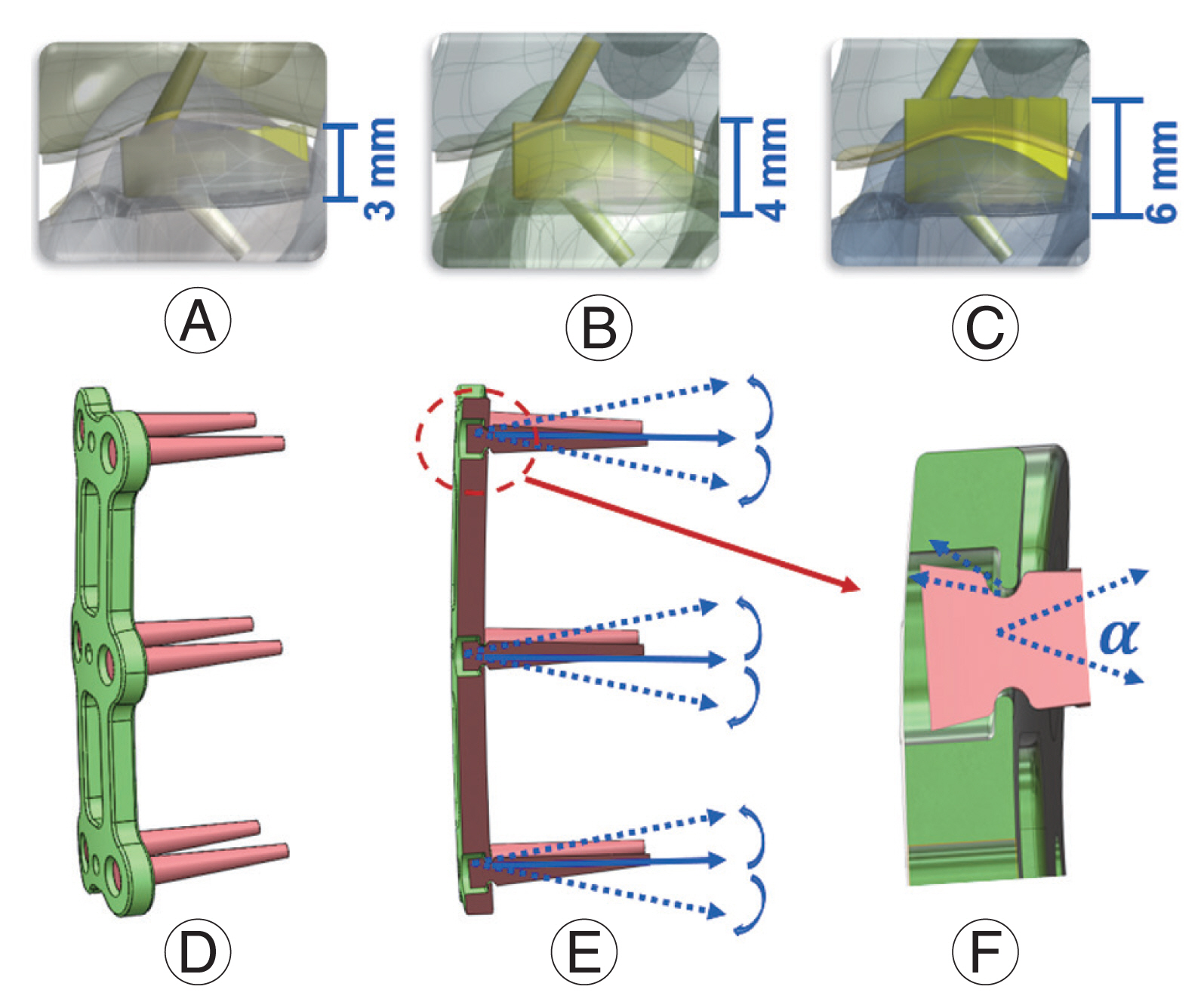
Additionally, the effect of biomechanical strength and increased contact area was examined on the maximum von Mises stress, migration, and subsidence between the cancellous bone, endplate, and implanted cage [50]. The newly constructed models revealed that a 1 mm embedding depth appeared to be the best balance of mechanical strength and contact area, resulting in the most favorable stability (Fig. 2). The friction between the cage and the endplate was considered to be constant, which is one of the studies’ shortcomings. Moussa et al. [42] considered variable porosity cages in the spine model and they demonstrated the advantage of lowering stress (up to 14%) and strain (up to 21.7%) under severe loading combinations. Additionally, Park et al. [51] observed that using more screws reduced the probability of sinking, though not significantly. Although not significantly, increasing the screw angle decreased the probability of sinking in the allograft spacer and the screws [52]. Different fixation methods improved stability in some areas of the fusion site but worsened stability in others. Screw loosening generally increased as the plate length increased [52]. Micromotion and subsidence are lessened by rotational dynamic plating, yet too much tolerance for rotational freedom in the screws eventually becomes detrimental [53]. Segmental plating decreased the chance of screw pullout post-surgery [54].

Specificity and Inclusivity in Models

Investigators must exercise judgment when evaluating the accuracy of models. Modeling more than is necessary is ineffective and can obscure the crucial information required to comprehend a particular circumstance. Models that are overly simplified or reduced in detail can produce false results or simply leave out important elements that would provide more information about the biomechanical state of the cervical spine.
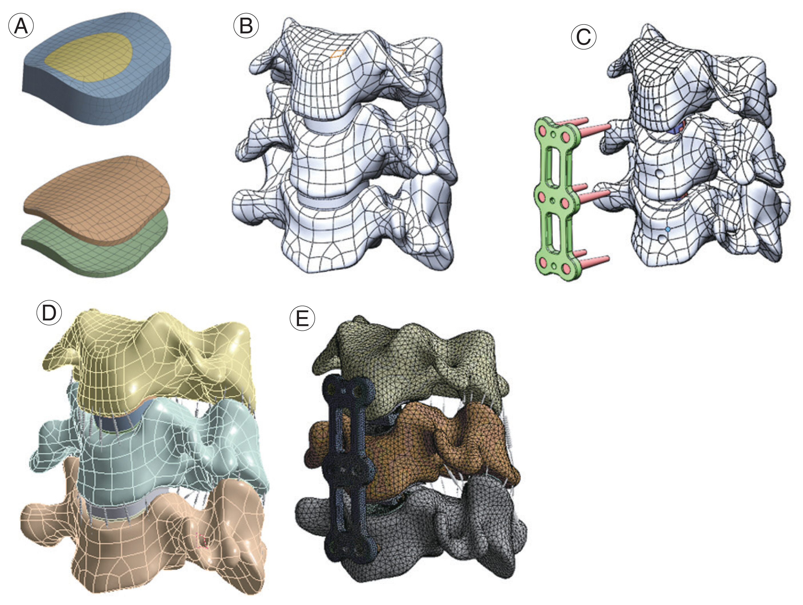
The majority of the FEA models currently utilized in literature are stitched together from patients’ CT data in mimics and meshed in a structural analysis preprocessor such as software ANSA or Hypermesh [55] (Fig. 3). As a result, the results of the FEA reflect the variation in the patient’s cervical geometry. This does not create any noticeable alteration in results. Examples of both fairly simplified parametric models and more complicated models with the muscle represented as solid parts are provided. Validated models, though varying in execution, do yield accurate outcomes. Execution differences, however, provide a wide range of outcomes that help resolve various cervical spine disorders.

1. Segmented spine models

The elimination of simulated junctions has proven to be one of the most significant reductions possible in ACDF models. When appropriate, modeling a collection of segments rather than the entire cervical spine has been the norm.
Typically, vertebra-disc-vertebra models of spinal segments are often compared to experimental data demonstrating the effects of simple quasi-static pressure on the biomechanical behavior of local tissues. To explore intervertebral disc stress distribution and pressure under compressive load, Belytschko et al. [56] created the first simplified axisymmetric model of a human spine. All models were linearly elastic, with the exception of the fiber loops, which were linearly orthotropic.
The first important cervical segmental model was created by Yoganandan et al. [13] using the geometry of the C4–C6 sections from CT scans. The material properties employed in the model were based on the model’s calibration to experimental data and the material models of the AF and nucleus pulposus were both considered as isotropic linear elastic materials. In comparison to the experimental data, the model performed well. Three years later, Kumaresan et al. [57] improved this model by including a more accurate model of the AF and a detailed model of the synovial facet joint. Intervertebral discs utilizing this new anisotropic AF model displayed a significant improvement over the experimental data compared to those constructed with linear composite AF.

2. Full cervical spine models

Compared to their counterparts, full cervical spine models are very uncommon in the literature. These are typically carried out to achieve results that would otherwise be impossible to achieve or to include extra, typically unaccounted-for systems like the muscles. The full cervical spine model usually focused on the global motion of the head rather than local tissue, unlike spinal segment models. In order to imitate the behavior of a real being, Williams and Belytschko [58] designed the cervical spine model with six degrees of freedom springs for shock loading conditions. It was successful at simulating the movements of the volunteer test subjects’ heads during frontal and lateral impacts by using active muscles. By representing intervertebral discs and spinal ligaments with solid parts and connecting them to streamlined vertebrae, Kleinberger [59] developed a full cervical spine model. However, there are some limitations in that the model did not account for muscle tissue, and the intervertebral disc was presumptively made of a single substance. The simplification of the discs seems to be a commonality as Holzapfel et al. [60] failed to consider the viscoelastic effect of the AF laminae model in their full spine model.
De Jager et al. [61] adapted and executed a head-neck model with the integrated multibody finite element code, which van der Horst [62] additionally advanced as a multi-body model. The first use of tissue models was made by Deng et al. [63] who used nonlinear, viscoelastic FE elements to represent tissue under dynamic conditions rather than calibrated or assumed attributes. Active muscles were also incorporated into the Hill muscle model offering realistic muscle force and direction during neck flexion. Each cervical spine muscle is represented in this model by both an active component and a passive one. This is ideal for simulating many neck impact scenarios as they typically involve active muscle behavior.

Conclusions

In this study, the material property models and cervical spine models were reviewed. Great progress has been recorded, even though less effort has been devoted to developing FE models of the cervical spine than developing FE models of the lumbar or thoracic spine. The papers discussed here can offer fundamental knowledge for the creation of general models; however, a trend is emerging toward the incorporation of detailed joint models into motion-driven musculoskeletal models to estimate stress/strain and contact pressure on joints in diverse processes.

Acknowledgments

This research was supported by the Boca Raton Regional Hospital Foundation (award # SP 19-579).

Notes

Conflict of Interest

No potential conflict of interest relevant to this article was reported.

Author Contributions

Data acquisition: ML; analysis of data: ML; drafting of the manuscript: ML; conception and design: ML; critical revision: ML, RP, UD, JD, TO, CT, FV; administrative support: CT, FV; and supervision: CT, FV.

Fig. 1
The micromotion field (A) and subsidence field (B) between the C45 bottom endplate and cage under the flexion situation.
asj-2022-0295f1.jpg
Fig. 2
(A) C4C6 segment three-dimensional (3D) finite element (FE) with the implanted cage; (B) C4C6 segment 3D FE with the cage embedded 1 mm; (C) C4C6 segment 3D FE with the cage embedded 3 mm into the endplate/vertebra. (D) Schematic of dynamic plate model with range of motion of screws; (E) section view of the dynamic plate; and (F) geometry differences for the 18°, 28°, and 38° (α) dynamic plate.
asj-2022-0295f2.jpg
Fig. 3
(A) Mesh of the disc and endplate; (B) C3–C5 segment three-dimensional finite element model with original disc and endplate; (C) the endplate was partially removed after implant cage; (D) C5 bottom edge was fixed and the moment was applied in the top surface of C3; (E) anterior longitudinal ligament, posterior longitudinal ligament, and disc were removed while the plate and cage screws were implanted.
asj-2022-0295f3.jpg
Table 1
Details the material model and properties of the main anatomical structures in the cervical spine, as presented in the literature
Spine component Material model (element type) Modulus (unit: MPa) Poisson’s ratio References
Cortical bone Isotropic elastic (solid) 16,800 0.3 Kim et al. [15] (2018)
15,000 0.2 Brolin et al. [20] (2004)
12,000 0.3 Kim et al. [15] (2018)
12,000 0.29 Kim et al. [15] (2018); Zhang et al. [19] (2005)
10,000 0.3 Kim et al. [15] (2018); Natarajan et al. [18] (2000)
Orthotropic elastic (shell) 11,300 (Exx); 11,300 (Eyy); 22,000 (Ezz); 3,800 (Gxy); 5,400 (Gyz); 5,400 (Gxz) 0.484 (vxy); 0.203 (vyz); 0.203 (vxz) Nikkhoo et al. [23] (2019)
9,600 (E11); 9,600 (E22); 17,800 (E33); 3,097 (G12); 3,510 (G13); 3,510 (G23) 0.55 (v12); 0.30 (v13); 0.30 (v23) Li et al. [28] (2010); Qi et al. [17] (2016)
Cancellous bone Isotropic elastic (solid) 500 0.2 Brolin et al. [20] (2004)
450 0.29 Kim et al. [15] (2018); Zhang et al. [19] (2005)
450 0.25 Kim et al. [15] (2018)
450 0.2 Natarajan et al. [18] (2000)
100–300 0.1–0.3 Kim et al. [15] (2018)
100 0.2 Kim et al. [15] (2018)
Orthotropic elastic (solid) 144 (E11); 99 (E22); 344 (E33); 53 (G12); 45 (G13); 63 (G23) 0.23 (v12); 0.17 (v13); 0.11 (v23) Li et al. [28] (2010); Qi et al. [17] (2016)
140 (Exx); 140 (Eyy); 200 (Ezz); 48.3 (Gxy); 48.3 (Gyz); 48.3 (Gxz) 0.45 (vxy); 0.315 (vyz); 0.315 (vxz) Nikkhoo et al. [23] (2019)
Posterior bone Isotropic elastic (solid) 3,500 0.29 Kim et al. [15] (2018); Li et al. [28] (2010); Qi et al. [17] (2016); Zhang et al. [19] (2005)
3,500 0.25 Kim et al. [15] (2018); Natarajan et al. [18] (2000)
Endplate Isotropic elastic (solid) 5,600 0.3 Kim et al. [15] (2018)
2,000 0.4 Natarajan et al. [18] (2000)
600 0.3 Kim et al. [15] (2018)
500 0.40 Li et al. [28] (2010); Kim et al. [15] (2018); Qi et al. [17] (2016); Zhang et al. [19] (2005)
Facet cartilage Isotropic elastic (solid) 11 0.4 Natarajan et al. [18] (2000)
10.4 0.4 Kim et al. [15] (2018)
10 0.4 Kim et al. [15] (2018)
10 0.3 Brolin et al. [20] (2004)
Annulus fibrosus (ground) Isotropic elastic (solid) 1–4.8 - Kim et al. [15] (2018)
4.2 0.45 Kim et al. [15] (2018)
3.4 0.4 Kim et al. [15] (2018)
3 0.45 Brolin et al. [20] (2004)
Hill foam 4.2 0.45 Li et al. [28] (2010); Natarajan et al. [18] (2000); Qi et al. [17] (2016)
3.4 0.40 Zhang et al. [19] (2005); Li et al. [28] (2010)
3.4 0.40
0.348 (C10); 0.30 (D1) - Li et al. [28] (2010)
Hyperelastic: neo-Hookean 0.56 (C10); 0.14 (C01) - Li et al. [28] (2010)
Hyperelastic: Mooney-Rivlin 0.56 (C10); 0.14 (C01) 0.45 Nikkhoo et al. [23] (2019)
4 0.45 Ke et al. [32] (2021)
Ground: degenerated 450 0.3 Li et al. [28] (2010)
Orthotropic elastic (shell) 500 - Kim et al. [15] (2018)
Rebar 500 0.3 Nikkhoo et al. [23] (2019)
Rebar truss 450 0.3 Kim et al. [15] (2018); Qi et al. [17] (2016)
30 (E1); 6 (E2) 0.016 Brolin et al. [20] (2004)
110 0.3 Kim et al. [15] (2018)
450 0.3 Natarajan et al. [18] (2000)
Nonlinear stress-strain 1 0.4999 Brolin et al. [20] (2004)
Solid 3.4 - Kim et al. [15] (2018)
Nucleus pulposus Solid 3.0 0.499 Natarajan et al. [18] (2000)
1 0.499 Li et al. [28] (2010); Qi et al. [17] (2016)
1 0.49 Zhang et al. [19] (2005); Kim et al. [15] (2018)
Hyperelastic: Mooney-Rivlin 0.12 (C10); 0.03 (C01) - Li et al. [28] (2010)
0.12 (C10); 0.09 (C01) 0.4999 Nikkhoo et al. [23] (2019)
Hyperelastic: Mooney-Rivlin 1,720 (K) - Kim et al. [15] (2018)
Fluid 4 0.49 Ke et al. [32] (2021)
Table 2
Details the material model and properties of the cervical spine ligaments as presented in the literature
Spine component Material model Properties References
ALL Spring Nonlinear force: displacement Kim et al. [15] (2018)
(5–13):(100–300) (mm: N) Brolin et al. [20] (2004)
Truss (nonlinear hyperelastic material) 10 MPa/0.30 Kim et al. [15] (2018)
Spar (nonlinear tension-only) 54.5 MPa Li et al. [28] (2010)
30.0 MPa Qi et al. [17] (2016)
30.0 MPa (CSA=6) Zhang et al. [19] (2005)
Spar (nonlinear stress-strain) 15–30 MPa/0.3 Natarajan et al. [18] (2000)
PLL Spring Nonlinear force: displacement Kim et al. [15] (2018)
(0–20):(0–160) (mm: N) Brolin et al. [20] (2004)
Truss (nonlinear hyperelastic material) 10 MPa/0.30 Kim et al. [15] (2018)
Spar (nonlinear tension-only) 20.0 MPa Li et al. [28] (2010); Qi et al. [17] (2016)
20.0 MPa (CSA=5) Zhang et al. [19] (2005)
Spar (nonlinear stress-strain) 10–20 MPa/0.3 Natarajan et al. [18] (2000)
LF Spring Nonlinear force: displacement Kim et al. [15] (2018)
(5–7):(20–150) (mm: N) Brolin et al. [20] (2004)
Truss (nonlinear hyperelastic material) 1.5 MPa/0.30 Kim et al. [15] (2018)
Spar (nonlinear tension-only) 1.5 MPa Li et al. [28] (2010); Qi et al. [17] (2016)
10 MPa (CSA=10) Zhang et al. [19] (2005)
Spar (nonlinear stress-strain) 5–10 MPa/0.3 Natarajan et al. [18] (2000)
CL Spring Nonlinear force: displacement Kim et al. [15] (2018)
(4–14):(80–340) (mm: N) Brolin et al. [20] (2004)
Truss (nonlinear hyperelastic material) 10 MPa/0.30 Kim et al. [15] (2018)
Spar (nonlinear tension-only) 20.0 MPa Li et al. [28] (2010); Qi et al. [17] (2016)
20.0 MPa (CSA=5) Zhang et al. [19] (2005)
Spar (nonlinear stress-strain) 7–30 MPa/0.3 Natarajan et al. [18] (2000)
ISL Spring Nonlinear force: displacement Kim et al. [15] (2018)
(5–9):(35–39) (mm: N) Brolin et al. [20] (2004)
Truss (nonlinear hyperelastic material) 1.5 MPa/0.30 Kim et al. [15] (2018)
Spar (nonlinear tension-only) 1.5 MPa Li et al. [28] (2010); Qi et al. [17] (2016)
10 MPa (CSA=10) Zhang et al. [19] (2005)
Spar (nonlinear stress-strain) 4–8 MPa/0.3 Natarajan et al. [18] (2000)
SSL Spring Nonlinear force: displacement Kim et al. [15] (2018)
Truss (nonlinear hyperelastic material) 1.5 MPa/0.30 Kim et al. [15] (2018)
Spar (nonlinear tension-only) 1.5 MPa Qi et al. [17] (2016)
1.5 MPa (CSA=5) Zhang et al. [19] (2005)

CSA, cross-sectional area; ALL, anterior longitudinal ligament; PLL, posterior longitudinal ligament; LF, ligament flavum; CL, capsular ligament; ISL, interspinous ligament; SSL, supraspinous ligament.

Table 3
Details the material models and properties of the cervical muscles as presented in the literature
Spine component Properties (geometry) (Nonlinear stress: force) References
Sternocleidomastoid (active) 4.92 cm2 (PCSA); 51 mm (L_opt) 50 (N/cm2): 82 N Brolin et al. [33] (2005)
4.9 cm2 (PCSA) 50 (N/cm2): 246.0 N Hedenstierna [34] (2008)
Sternocleidomastoid (passive) 4.9 cm2 (PCSA); 192 mm (L_opt); 39.5 g (mass) - Hedenstierna [34] (2008)
4.9 cm2 (PCSA); 190 mm (L_opt); 40.4 g (mass) - Hedenstierna [34] (2008)
Longus cervicis (active) 1.37 cm2 (PCSA); 60 mm (L_opt) 50 (N/cm2): 17 N Brolin et al. [33] (2005)
Longus capitis (active) 1.4 cm2 (PCSA) 50 (N/cm2): 68.5 N Hedenstierna [34] (2008)
Longus capitis (passive) 1.7 cm2 (PCSA); 104 mm (L_opt); 4.9 g (mass) - Hedenstierna [34] (2008)
1.7 cm2 (PCSA); 92 mm (L_opt); 3.7 g (mass) - Hedenstierna [34] (2008)
1.7 cm2 (PCSA); 115 mm (L_opt); 8.6 g (mass) - Hedenstierna [34] (2008)
Longus colli (passive) 1.4 cm2 (PCSA); 104 mm (L_opt); 6.9 g (mass) - Hedenstierna [34] (2008)
1.4 cm2 (PCSA); 188 mm (L_opt); 10.2 g (mass) - Hedenstierna [34] (2008)
Longus colli inferior (active) 0.8 cm2 (PCSA) 50 (N/cm2): 40.0 N Hedenstierna [34] (2008)
Longus colli longitudinal (active) 0.9 cm2 (PCSA) 50 (N/cm2): 45.0 N Hedenstierna [34] (2008)
Longus colli superior (active) 0.4 cm2 (PCSA) 50 (N/cm2): 20.0 N Hedenstierna [34] (2008)
R. A. Ma. (active) 1.68 cm2 (PCSA); 85 mm (L_opt) 50 (N/cm2): 21 N Brolin et al. [33] (2005)
R. A. Mi. (active) 0.92 cm2 (PCSA); 30 mm (L_opt) 50 (N/cm2): 46 N Brolin et al. [33] (2005)
Scalene (active) 4.29 cm2 (PCSA); 120 mm (L_opt) 50 (N/cm2): 18 N Brolin et al. [33] (2005)
Scalene anterior (active) 1.9 cm2 (PCSA) 50 (N/cm2): 94.0 N Hedenstierna [34] (2008)
Scalene anterior (passive) 4.3 cm2 (PCSA); 91 mm (L_opt); 7.8 g (mass) - Hedenstierna [34] (2008)
4.3 cm2 (PCSA); 5.6 g (mass) - Hedenstierna [34] (2008)
4.3 cm2 (PCSA); 115 mm (L_opt); 8.5 g (mass) - Hedenstierna [34] (2008)
Scalene medius (active) 1.4 cm2 (PCSA) 50 (N/cm2): 68.0 N Hedenstierna [34] (2008)
Scalene medius (passive) 4.3 cm2 (PCSA); 82 mm (L_opt); 5.0 g (mass) - Hedenstierna [34] (2008)
4.3 cm2 (PCSA); 10.6 g (mass) - Hedenstierna [34] (2008)
4.3 cm2 (PCSA); 139 mm (L_opt); 14.4 g (mass) - Hedenstierna [34] (2008)
Scalene posterior (active) 1.1 cm2 (PCSA) 50 (N/cm2): 52.5 N Hedenstierna [34] (2008)
Scalene posterior (passive) 4.3 cm2 (PCSA); 106 mm (L_opt); 8.5 g (mass) - Hedenstierna [34] (2008)
4.3 cm2 (PCSA); 10.8 g (mass) - Hedenstierna [34] (2008)
4.3 cm2 (PCSA); 84 mm (L_opt); 6.7 g (mass) - Hedenstierna [34] (2008)
Suboccipital (active) 1.00 cm2 (PCSA); 30 mm (L_opt) 50 (N/cm2): 50 N Brolin et al. [33] (2005)
Semispinalis (active) 8.58 cm2 (PCSA); 27 mm (L_opt) 50 (N/cm2): 54 N Brolin et al. [33] (2005)
Semispinalis cervicis (active) 3.1 cm2 (PCSA) 50 (N/cm2): 153.0 N Hedenstierna [34] (2008)
Semispinalis cervicis (passive) 8.6 cm2 (PCSA); 167 mm (L_opt); 21.18 g (mass) - Hedenstierna [34] (2008)
8.6 cm2 (PCSA) - Hedenstierna [34] (2008)
8.6 cm2 (PCSA); 200 mm (L_opt); 24.2 g (mass) - Hedenstierna [34] (2008)
Semispinalis capitis (active) 5.5 cm2 (PCSA) 50 (N/cm2): 276.0 N Hedenstierna [34] (2008)
Semispinalis capitis (passive) 8.6 cm2 (PCSA); 223 mm (L_opt); 36.6 g (mass) - Hedenstierna [34] (2008)
8.6 cm2 (PCSA); 117 mm (L_opt); 38.5 g (mass) - Hedenstierna [34] (2008)
8.6 cm2 (PCSA); 285 mm (L_opt); 44.4 g (mass) - Hedenstierna [34] (2008)
Longissimus (active) 2.47 cm2 (PCSA); 35 mm (L_opt) 50 (N/cm2): 12 N Brolin et al. [33] (2005)
2.5 cm2 (PCSA) 50 (N/cm2): 123.5 N Hedenstierna [34] (2008)
Longissimus capitis (passive) 2.5 cm2 (PCSA); 376 mm (L_opt); 32.3 g (mass) - Hedenstierna [34] (2008)
2.5 cm2 (PCSA) - Hedenstierna [34] (2008)
2.5 cm2 (PCSA); 237 mm (L_opt); 16.6 g (mass) - Hedenstierna [34] (2008)
Longissimus cervicis (passive) 2.5 cm2 (PCSA); 268 mm (L_opt); 32.5 g (mass) - Hedenstierna [34] (2008)
2.5 cm2 (PCSA) - Hedenstierna [34] (2008)
2.5 cm2 (PCSA); 16.6 g (mass) - Hedenstierna [34] (2008)
Splenius (active) 4.52 cm2 (PCSA); 80 mm (L_opt) 50 (N/cm2): 23 N Brolin et al. [33] (2005)
Splenius cervicis (active) 1.4 cm2 (PCSA) 50 (N/cm2): 71.5 N Hedenstierna [34] (2008)
Splenius cervicis (passive) 4.5 cm2 (PCSA); 188 mm (L_opt); 14.6 g (mass) - Hedenstierna [34] (2008)
4.5 cm2 (PCSA); 147 mm (L_opt) - Hedenstierna [34] (2008)
4.5 cm2 (PCSA); 290 mm (L_opt); 15.5 g (mass) - Hedenstierna [34] (2008)
Splenius capitis (active) 3.1 cm2 (PCSA) 50 (N/cm2): 154.5 N Hedenstierna [34] (2008)
Splenius capitis (passive) 4.5 cm2 (PCSA); 155 mm (L_opt); 17.6 g (mass) - Hedenstierna [34] (2008)
4.5 cm2 (PCSA); 123 mm (L_opt); 42.9 g (mass) - Hedenstierna [34] (2008)
4.5 cm2 (PCSA); 260 mm (L_opt); 32.1 g (mass) - Hedenstierna [34] (2008)
Levator scapulae (active) 3.12 cm2 (PCSA); 41 mm (L_opt) 50 (N/cm2): 39 N Brolin et al. [33] (2005)
3.1 cm2 (PCSA) 50 (N/cm2): 156.0 N Hedenstierna [34] (2008)
Levator scapulae (passive) 3.1 cm2 (PCSA); 232 mm (L_opt); 29.2 g (mass) - Hedenstierna [34] (2008)
3.1 cm2 (PCSA); 82 mm (L_opt) - Hedenstierna [34] (2008)
3.1 cm2 (PCSA); 160 mm (L_opt); 47.7 g (mass) - Hedenstierna [34] (2008)
Trapezius (active) 13.73 cm2 (PCSA); 41 mm (L_opt) 50 (N/cm2): 76 N Brolin et al. [33] (2005)
10.0 cm2 (PCSA) 50 (N/cm2): 498.0 N Hedenstierna [34] (2008)
Trapezius (passive) 13.7 cm2 (PCSA); 460 mm (L_opt); 180.0 g (mass) - Hedenstierna [34] (2008)
13.7 cm2 (PCSA); 391 mm (L_opt); 172.4 g (mass) - Hedenstierna [34] (2008)
13.7 cm2 (PCSA); 591 mm (L_opt); 102.3 g (mass) - Hedenstierna [34] (2008)
Interspinuous (active) 1.00 cm2 (PCSA); 14 mm (L_opt) 50 (N/cm2): 50 N Brolin et al. [33] (2005)
Hyoid superior (active) 1.02 cm2 (PCSA); 30 mm (L_opt) 50 (N/cm2): 51 N Brolin et al. [33] (2005)
1.1 cm2 (PCSA) 50 (N/cm2): 56.0 N Hedenstierna [34] (2008)
4.3 cm2 (PCSA) Hedenstierna [34] (2008)
Hyoid inferior (active) 1.33 cm2 (PCSA); 120 mm (L_opt) 50 (N/cm2): 67 N Brolin et al. [33] (2005)
1.2 cm2 (PCSA) 50 (N/cm2): 61.5 N Hedenstierna [34] (2008)
Hyoid inferior (passive) 1.0 cm2 (PCSA); 105 mm (L_opt); 15.2 g (mass) - Hedenstierna [34] (2008)
Multifidus (active) 1.33 cm2 (PCSA) 50 (N/cm2): 67.0 N Hedenstierna [34] (2008)
Multifidus (passive) 440 mm (L_opt); 55.0 g (mass) - Hedenstierna [34] (2008)
Iliocostalis (active) 1.0 cm2 (PCSA) 50 (N/cm2): 52.0 N Hedenstierna [34] (2008)
Iliocostalis cervicis (passive) 2.5 cm2 (PCSA) - Hedenstierna [34] (2008)
2.5 cm2 (PCSA); 150 mm (L_opt) - Hedenstierna [34] (2008)
2.5 cm2 (PCSA); 4.4 g (mass) - Hedenstierna [34] (2008)
Rectus capitis posterior minor (active) 0.9 cm2 (PCSA) 50 (N/cm2): 46.0 N Hedenstierna [34] (2008)
Rectus capitis posterior minor (passive) 1.0 cm2 (PCSA); 48 mm (L_opt); 3.6 g (mass) - Hedenstierna [34] (2008)
1.0 cm2 (PCSA); 1.0 g (mass) - Hedenstierna [34] (2008)
1.0 cm2 (PCSA); 33 mm (L_opt); 1.5 g (mass) - Hedenstierna [34] (2008)
Rectus capitis posterior major (active) 1.7 cm2 (PCSA) 50 (N/cm2): 84.0 N Hedenstierna [34] (2008)
Rectus capitis posterior major (passive) 1.0 cm2 (PCSA); 55 mm (L_opt); 4.0 g (mass) - Hedenstierna [34] (2008)
1.0 cm2 (PCSA); 3.5 g (mass) - Hedenstierna [34] (2008)
1.0 cm2 (PCSA); 61 mm (L_opt); 3.46 g (mass) - Hedenstierna [34] (2008)
Rectus capitis anterior (active) 0.7 cm2 (PCSA) 50 (N/cm2): 32.5 N Hedenstierna [34] (2008)
Rectus capitis anterior (passive) 0.9 cm2 (PCSA); 33 mm (L_opt); 0.6 g (mass) - Hedenstierna [34] (2008)
Rectus capitis lateralis (active) 0.7 cm2 (PCSA) 50 (N/cm2): 32.5 N Hedenstierna [34] (2008)
Rectus capitis lateralis (passive) 0.9 cm2 (PCSA); 29 mm (L_opt); 1.0 g (mass) - Hedenstierna [34] (2008)
Oblique capitis inferior (active) 1.9 cm2 (PCSA) 50 (N/cm2): 97.5 N Hedenstierna [34] (2008)
Oblique capitis inferior (passive) 1.0 cm2 (PCSA); 57 mm (L_opt); 4.6 g (mass) - Hedenstierna [34] (2008)
1.0 cm2 (PCSA); 44 mm (L_opt); 5.1 g (mass) - Hedenstierna [34] (2008)
1.0 cm2 (PCSA); 51 mm (L_opt); 3.3 g (mass) - Hedenstierna [34] (2008)
Oblique capitis superior (active) 0.9 cm2 (PCSA) 50 (N/cm2): 44.0 N Hedenstierna [34] (2008)
Oblique capitis superior (passive) 1.0 cm2 (PCSA); 42 mm (L_opt); 2.6 g (mass) - Hedenstierna [34] (2008)
1.0 cm2 (PCSA); 2.5 g (mass) - Hedenstierna [34] (2008)
1.0 cm2 (PCSA); 51 mm (L_opt); 1.6 g (mass) - Hedenstierna [34] (2008)
All passive muscles (discrete) Bilinear elastic model with non-linear damper 1.8 MPa (modulus); 1,060 kg/m3 (density); 0.5 (Poisson’s) Hedenstierna [34] (2008)
All passive muscles (muscle solids) Hyperelastic: Ogden with linear viscoelasticity 13,337 (meu); 14.5 (alpha) Hedenstierna [34] (2008)

PCSA, physiological cross-sectional area; L_opt, optimal fiber length.

References

1. Berthoz A, Graf W, Vidal PP. The head-neck sensory motor system. New York (NY): Oxford University Press; 1992.

2. Belavy DL, Adams M, Brisby H, et al. Disc herniations in astronauts: what causes them, and what does it tell us about herniation on earth? Eur Spine J 2016 25:144–54.
crossref pmid pdf
3. Coakwell MR, Bloswick DS, Moser R Jr. High-risk head and neck movements at high G and interventions to reduce associated neck injury. Aviat Space Environ Med 2004 75:68–80.
pmid
4. Nouri A, Tetreault L, Singh A, Karadimas SK, Fehlings MG. Degenerative cervical myelopathy: epidemiology, genetics, and pathogenesis. Spine (Phila Pa 1976) 2015 40:E675–93.
pmid
5. Kim SW, Limson MA, Kim SB, et al. Comparison of radiographic changes after ACDF versus Bryan disc arthroplasty in single and bi-level cases. Eur Spine J 2009 18:218–31.
crossref pmid pmc pdf
6. Patwardhan AG, Khayatzadeh S, Havey RM, et al. Cervical sagittal balance: a biomechanical perspective can help clinical practice. Eur Spine J 2018 27(Suppl 1): 25–38.
crossref pmid pdf
7. Le H, Thongtrangan I, Kim DH. Historical review of cervical arthroplasty. Neurosurg Focus 2004 17:E1.
crossref
8. Grauvogel J, Scheiwe C, Kaminsky J. Use of Piezosurgery for removal of retrovertebral body osteophytes in anterior cervical discectomy. Spine J 2014 14:628–36.
crossref pmid
9. Oppenheimer JH, DeCastro I, McDonnell DE. Minimally invasive spine technology and minimally invasive spine surgery: a historical review. Neurosurg Focus 2009 27:E9.
crossref pmid pmc
10. Jacobs W, Willems PC, Kruyt M, et al. Systematic review of anterior interbody fusion techniques for single- and double-level cervical degenerative disc disease. Spine (Phila Pa 1976) 2011 36:E950–60.
crossref pmid
11. Denaro V, Di Martino A. Cervical spine surgery: an historical perspective. Clin Orthop Relat Res 2011 469:639–48.
crossref pmid pmc
12. Panjabi MM, Cholewicki J, Nibu K, Grauer J, Babat LB, Dvorak J. Critical load of the human cervical spine: an in vitro experimental study. Clin Biomech (Bristol, Avon) 1998 13:11–7.
crossref pmid
13. Yoganandan N, Kumaresan S, Voo L, Pintar FA. Finite element applications in human cervical spine modeling. Spine (Phila Pa 1976) 1996 21:1824–34.
crossref pmid
14. Goel VK, Ramirez SA, Kong W, Gilbertson LG. Cancellous bone Young’s modulus variation within the vertebral body of a ligamentous lumbar spine: application of bone adaptive remodeling concepts. J Biomech Eng 1995 117:266–71.
crossref pmid pdf
15. Kim YH, Khuyagbaatar B, Kim K. Recent advances in finite element modeling of the human cervical spine. J Mech Sci Technol 2018 32:1–10.
crossref pdf
16. Kopperdahl DL, Keaveny TM. Yield strain behavior of trabecular bone. J Biomech 1998 31:601–8.
crossref pmid
17. Qi Y, Lewis G. Influence of assigned material combination in a simulated total cervical disc replacement design on kinematics of a model of the full cervical spine: a finite element analysis study. Biomed Mater Eng 2016 27:633–46.
crossref pmid
18. Natarajan RN, Chen BH, An HS, Andersson GB. Anterior cervical fusion: a finite element model study on motion segment stability including the effect of osteoporosis. Spine (Phila Pa 1976) 2000 25:955–61.
pmid
19. Zhang QH, Teo EC, Ng HW. Development and validation of a CO-C7 FE complex for biomechanical study. J Biomech Eng 2005 127:729–35.
pmid
20. Brolin K, Halldin P. Development of a finite element model of the upper cervical spine and a parameter study of ligament characteristics. Spine (Phila Pa 1976) 2004 29:376–85.
crossref pmid
21. Kumaresan S, Yoganandan N, Pintar FA. Finite element modeling approaches of human cervical spine facet joint capsule. J Biomech 1998 31:371–6.
crossref pmid
22. Gilbertson LG, Goel VK, Kong WZ, Clausen JD. Finite element methods in spine biomechanics research. Crit Rev Biomed Eng 1995 23:411–73.
crossref pmid
23. Nikkhoo M, Cheng CH, Wang JL, et al. Development and validation of a geometrically personalized finite element model of the lower ligamentous cervical spine for clinical applications. Comput Biol Med 2019 109:22–32.
crossref pmid
24. Yang KH, Kish VL. Compressibility measurement of human intervertebral nucleus pulposus. J Biomech 1988 21:865.
crossref
25. Iatridis JC, Weidenbaum M, Setton LA, Mow VC. Is the nucleus pulposus a solid or a fluid?: mechanical behaviors of the nucleus pulposus of the human intervertebral disc. Spine (Phila Pa 1976) 1996 21:1174–84.
crossref pmid
26. Hill R. Aspects of invariance in solid mechanics. Adv Appl Mech 1978 18:1–72.
crossref
27. Storakers B. On material representation and constitutive branching in finite compressible elasticity. J Mech Phys Solids 1986 34:125–45.
crossref
28. Li Y, Lewis G. Influence of the constitutive material behavior model assigned to the annulus fibrosus and the nucleus pulposus on the biomechanical performance of a model of the cervical spine: a finite element analysis study. J Mech Med Biol 2010 10:151–66.
crossref
29. Cassidy JJ, Hiltner A, Baer E. Hierarchical structure of the intervertebral disc. Connect Tissue Res 1989 23:75–88.
crossref pmid
30. Eberlein R, Holzapfel GA, Schulze-Bauer CA. An anisotropic model for annulus tissue and enhanced finite element analyses of intact lumbar disc bodies. Comput Methods Biomech Biomed Engin 2001 4:209–29.
crossref
31. Yoganandan N, Haffner M, Maiman DJ, et al. Epidemiology and injury biomechanics of motor vehicle related trauma to the human spine. SAE Trans 1989 98:1790–809.
crossref
32. Ke W, Chen C, Wang B, et al. Biomechanical evaluation of different surgical approaches for the treatment of adjacent segment diseases after primary anterior cervical discectomy and fusion: a finite element analysis. Front Bioeng Biotechnol 2021 9:718996.
crossref pmid pmc
33. Brolin K, Halldin P, Leijonhufvud I. The effect of muscle activation on neck response. Traffic Inj Prev 2005 6:67–76.
crossref pmid
34. Hedenstierna S. 3D finite element modeling of cervical musculature and its effect on neck injury prevention [dissertation] Huddinge: Royal Institute of Technology. 2008

35. Polikeit A, Ferguson SJ, Nolte LP, Orr TE. Factors influencing stresses in the lumbar spine after the insertion of intervertebral cages: finite element analysis. Eur Spine J 2003 12:413–20.
crossref pmid pmc pdf
36. Yoganandan N, Kumaresan S, Pintar FA. Biomechanics of the cervical spine: part 2. cervical spine soft tissue responses and biomechanical modeling. Clin Biomech (Bristol, Avon) 2001 16:1–27.
crossref pmid
37. Winters JM, Stark L. Analysis of fundamental human movement patterns through the use of in-depth antagonistic muscle models. IEEE Trans Biomed Eng 1985 32:826–39.
crossref pmid
38. Winters JM, Stark L. Estimated mechanical properties of synergistic muscles involved in movements of a variety of human joints. J Biomech 1988 21:1027–41.
crossref pmid
39. Winters JM,Hill-based muscle models: a systems engineering perspective. Winters JM, Woo SL, editors. Multiple muscle systems: biomechanics and movement organization. New York (NY): Springer; 1990. p.69–93.
crossref
40. Sun J, Wang Q, Cai D, et al. A lattice topology optimization of cervical interbody fusion cage and finite element comparison with ZK60 and Ti-6Al-4V cages. BMC Musculoskelet Disord 2021 22:390.
crossref pmid pmc pdf
41. Liu J, Wang R, Wang H, et al. Biomechanical comparison of a new memory compression alloy plate versus traditional titanium plate for anterior cervical discectomy and fusion: a finite element analysis. Biomed Res Int 2020 2020:5769293.
crossref pmid pmc pdf
42. Moussa A, Tanzer M, Pasini D. Cervical fusion cage computationally optimized with porous architected titanium for minimized subsidence. J Mech Behav Biomed Mater 2018 85:134–51.
crossref pmid
43. Huang H, Liu J, Wang L, Fan Y. A critical review on the biomechanical study of cervical interbody fusion cage. Med Novel Technol Devices 2021 11:100070.
crossref
44. Choi J, Che L, Kim KN, et al. A finite element analysis of a biodegradable cervical plate and screw system. Asian J Pain 2017 3:12–6.
crossref pdf
45. Gayzik FS, Moreno DP, Vavalle NA, Rhyne AC, Stitzel J. Development of a full human body finite element model for blunt injury prediction utilizing a multi-modality medical imaging protocol. In: Proceedings of the 12th International LS-DYNA Users Conference; 2012 Jun 3–5; Dearborn, USA. Livermore (CA): Ansys. 2012

46. Kumaresan S, Yoganandan N, Pintar FA, Maiman DJ. Finite element modeling of the cervical spine: role of intervertebral disc under axial and eccentric loads. Med Eng Phys 1999 21:689–700.
crossref pmid
47. Liang D, Tu GJ, Han YX, Guo DW. Accurate simulation of the herniated cervical intervertebral disc using controllable expansion: a finite element study. Comput Methods Biomech Biomed Engin 2021 24:897–904.
crossref pmid
48. Jalalian A, Gibson I, Tay EH. Computational biomechanical modeling of scoliotic spine: challenges and opportunities. Spine Deform 2013 1:401–11.
crossref pmid
49. Lin M, Shapiro SZ, Doulgeris J, Engeberg ED, Tsai CT, Vrionis FD. Cage-screw and anterior plating combination reduces the risk of micromotion and subsidence in multilevel anterior cervical discectomy and fusion-a finite element study. Spine J 2021 21:874–82.
crossref pmid
50. Lin M, Paul R, Shapiro SZ, et al. Biomechanical study of cervical endplate removal on subsidence and migration in multilevel anterior cervical discectomy and fusion. Asian Spine J 2022 16:615–24.
crossref pmid pmc pdf
51. Park KM, Jung TG, Jeong SJ, Lee SJ. Comparative study on biomechanical behavior of various cervical stand-alone cage designs. J Korean Soc Precis Eng 2016 33:943–50.
crossref
52. Kwon JW, Bang SH, Kwon YW, et al. Biomechanical comparison of the angle of inserted screws and the length of anterior cervical plate systems with allograft spacers. Clin Biomech (Bristol, Avon) 2020 76:105021.
crossref pmid
53. Lin M, Shapiro SZ, Engeberg ED, Tsai CT, Vrionis FD. Finite element analysis of the effect of dynamic plating on two-level anterior cervical discectomy fusion biomechanics. World Neurosurg 2022 163:e43–52.
crossref pmid
54. Kiapour A, Massaad E, Shin JH. 237. Individual plates vs single plate for multilevel fixation results in superior biomechanics in anterior cervical fusion surgery. Spine J 2020 20:S117.
crossref
55. Chen C, Cheng B, Huang C, Jiang B, Chen D, Tao X. Finite element analysis of cervical spinal nerve tissue tolerance to whiplash injury: a preliminary study. In: Proceedings of the FISITA 2012 World Automotive Congress; 2012 Nov 27–30; Beijing, China. Berlin: Springer. 2013 pp 433–48.
crossref
56. Belytschko T, Kulak RF, Schultz AB, Galante JO. Finite element stress analysis of an intervertebral disc. J Biomech 1974 7:277–85.
crossref pmid
57. Kumaresan S, Yoganandan N, Pintar FA. Finite element analysis of the cervical spine: a material property sensitivity study. Clin Biomech (Bristol, Avon) 1999 14:41–53.
crossref pmid
58. Williams JL, Belytschko TB. A three-dimensional model of the human cervical spine for impact simulation. J Biomech Eng 1983 105:321–31.
crossref pmid pdf
59. Kleinberger M. Application of finite element techniques to the study of cervical spine mechanics. Warrendale (PA): SAE International; 1993.

60. Holzapfel GA, Schulze-Bauer CA, Feigl G, Regitnig P. Single lamellar mechanics of the human lumbar anulus fibrosus. Biomech Model Mechanobiol 2005 3:125–40.
crossref pmid pdf
61. De Jager M, Sauren AA, Thunnissen J, Wismans JS. A three-dimensional head-neck model: validation for frontal and lateral impacts. J Passeng Cars 1994 103:1660–76.

62. Van der Horst MJ. Human head neck response in frontal, lateral and rear end impact loading: modelling and validation. Eindhoven: Technische Universiteit Eindhoven; 2002.

63. Deng YC, Li X, Liu Y. Modeling of the human cervical spine using finite element techniques. Warrendale (PA): SAE International; 1999.


ABOUT
ARTICLE CATEGORY

Browse all articles >

BROWSE ARTICLES
EDITORIAL POLICY
FOR CONTRIBUTORS
Editorial Office
Department of Orthopedic Surgery, Asan Medical Center, University of Ulsan College of Medicine
88, Olympic-ro 43-gil, Songpa-gu, Seoul 05505, Korea
Tel: +82-2-3010-3530    Fax: +82-2-3010-8555    E-mail: asianspinejournal@gmail.com                
Korean Society of Spine Surgery
27, Dongguk-ro, Ilsandong-gu, Goyang-si 10326, Korea
Tel: +82-31-966-3413    Fax: +82-2-831-3414    E-mail: office@spine.or.kr                

Copyright © 2024 by Korean Society of Spine Surgery.

Developed in M2PI

Close layer
prev next