Atlantoaxial Stabilization Using C1 Lateral Mass and C2 Pedicle/Translaminar Screw Fixation by Intraoperative C1- and C2-Direct-Captured Navigation with Preoperative Computed Tomography Images
Article information

Abstract
In C1–C2 posterior fixation, the C1 lateral mass and C2 pedicle/translaminar screw insertion under spine navigation have been used frequently. To avoid the risk of neurovascular damage in atlantoaxial stabilization, we assessed the safety and effectiveness of a preoperative computed tomography (CT) image-based navigation system with intraoperative independent C1 and C2 vertebral registration. It is ideal when a reference frame can be linked directly to the C1 posterior arch for C1-direct-captured navigation, but there is a mechanical challenge. A new spine clamp-tracker system was implemented recently, which allows reliable C1- and C2-direct-captured navigation in nine patients with traumatic C2 fractures. In this way, there was no misalignment of C1–C2 screws. C1 lateral mass screws were used except for one case, and translaminar screws were primarily used as an anchor for C2. The C1 lateral mass screw locations, which are 19 mm laterally from the C1 posterior arch’s center, are taken to be constant. However, there is one unusual circumstance in which using a C1 laminar hook instead of a C1 lateral mass screw appears to be a beneficial substitute. The increase of surgical accuracy for posterior C1–C2 screw fixation without cost constraints is significantly facilitated by intraoperative C1- and C2-direct-captured navigation with preoperative computed CT images.
Introduction
Trauma, congenital malformations, and inflammation can all lead to atlantoaxial instability or fracture/dislocation, which can cause potentially fatal neurovascular injury and require C1–C2 stabilization [1-3]. The Goel–Harms approach, also known as posterior fixation with C1 lateral mass screws (LMSs) and C2 pedicle screws (PSs), has been successfully employed for atlantoaxial fixation with outstanding clinical results comparable to those of the C1–C2 transarticular procedure [1,4]. The C1 LMS, which is utilized in the majority of illnesses where anchoring to C1 is required, was developed in 1994 for C1–C2 posterior fixation [5]. However, even after identifying flowing vertebral artery variants and adverse pedicle injuries including fracture and dislocation, the implantation of C2 PS still carries the risk of neurovascular injury. C2 translaminar screws (TLS) and C2 short pedicle/pars screws have been used as alternative methods when C2 PS placement is prohibited and have revealed satisfactory fusion rates and clinical outcomes [6-8]. The main benefits of C1 LMS–C2 TLS fixation over C1 LMS–C2 PS fusion are the ability to add posterior decompression in contrast to Magerl’s technique [9] and the ability to be reducible following screw setup.
Recently the development of image-guided navigation technology has resulted in significant changes in upper cervical surgery with high risk. The effectiveness of C1–C2 screw fixation using intraoperative computed tomography (CT)-based navigation such as the O-arm imaging system, has been described in several studies [10-12]. Regarding intraoperative CT-based navigation, financial constraints could provide a challenge. New research has examined the efficacy of techniques combining intraoperative registration of individual cervical vertebrae with preoperative CT [13]. Because it is mechanically challenging to attach a reference frame directly and securely to the slender C1 posterior arch, the clamp is often attached out of necessity to the C2 spinous process or Mayfield head frame outside of the operative field. In such a circumstance, precise navigation for C1 LMS, which represents the positional relationship of C1–C2 during surgery, is utterly impossible. Recently we introduced a new reference frame attached stably to the C1 posterior tubercle. This procedure allows the exact trajectory of C1 LMS to to be captured. The current study’s objectives are to describe our technique for positioning C1 LMS with a spine clamp-tracker securely and steadily, as well as to show how accurate it is for C1–C2 posterior fusion under preoperative CT-based navigation with intraoperative C1- and C2-direct-recorded registration. Additionally, we contrasted surgical cases utilizing individual C1- and C2-direct captured navigation with those utilizing solely C2-direct captured navigation in terms of operation duration, projected blood loss, and differences in screw insertion precision.
Technical Note
1. Materials and methods
Table 1 illustrates the clinical summary of 17 patients with C1–C2 posterior fusion. These patients have received C1–C2 posterior fusion treatment in our hospital since June 2016. Of those eight patients (group A) underwent C1–C2 posterior fusion under C2-direct-captured navigation from June 2016 to November 2019 and nine patients (group B) underwent individual C1- and C2-direct-captured navigation starting in January 2020. Of the eight patients in group A, three males, and five females were aged 34–88 years (mean, 70 years). The nine patients in group B, ranged in age from 45 to 92 years, with seven men and two women (mean, 70 years). The cause of onset was a falling-down or tumbling-down accident. After being transported in an ambulance, each patient was immediately hospitalized. Despite suffering a violent hit to their entire body, they, fortunately, did not have spinal cord injuries. A neck brace was attached to all the patients and elective surgeries were planned. Four patients in group A and five patients in group B were found to have type I traumatic spondylolisthesis, which is characterized by no displacement, no angulation, translation of less than 3 mm, and intact C2–3 disc, according to the classification of Levine and Edwards [14]. Type I (oblique avulsion fracture of the apex), type II (fracture at the junction of the body and the neck), and type III (fracture extends into the body of C2 and may involve the lateral facet) of the C2 odontoid fracture, according to the classification of Anderson and D’Alonzo [15], were each seen in one patient in group B, while type III was seen in three patients in group A. That atlantoaxial subluxation was observed in three patients in group A. That of os odontoideum was observed in one patient in group B. One case each in groups A and B involved a patient with C2 traumatic spondylolisthesis type I or III and bilateral C3 laminar fractures (compression extension type of Allen [16]).
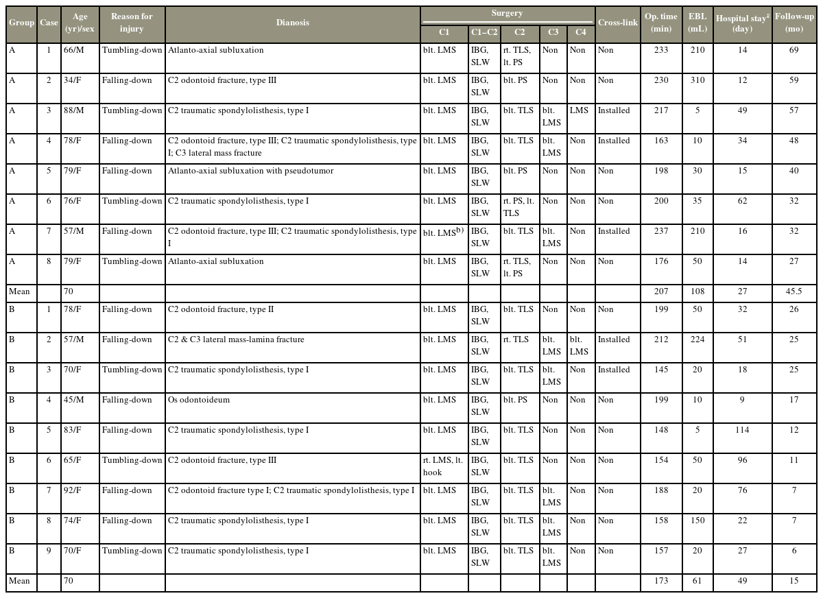
Summary of clinical characteristics of 17 patients with C1–C2 posterior fusion
2. Technical description
In Group A (Fig. 1), the clamp is attached to the C2 spinous process since it is challenging to steadily attach a spine clamp-tracker to the C1 posterior arch (Fig. 1A). The intraoperative cervical alignment does not necessarily reflect the alignment at the time of the preoperative CT shooting. During C2-direct-captured navigation, the position of the transverse foramen and the lateral mass on the axial profile can be validated (Fig. 1B), but C1 LMS needs to be watched to ensure that it doesn’t cross C1 posterior arch from the sagittal plane of fluorography (Fig. 1C). For group B (Figs. 2–5), three bony locations were chosen as point registration for C1-direct-captured navigation before the insertion of C1 LMS. One was the center of the C1 posterior tubercle and two were C1 LMS insertion points 19 mm lateral from the center corresponding to the transitional point of the posterior arch and lateral mass [17]. Stryker’s SpineMap 3D 3.1 navigation software was used to digitize these three points after the spine clamp with a tracker (gross weight 110 g, nGenius spine clamp; Stryker, Tokyo, Japan) was tightly fixed to the C1 posterior tubercle (Figs. 2C, 4C). Surface matchings of the C1 posterior arch were then performed to increase precision. Precision was raised to 0.4 mm or less by tracing the bony surface of the C1 posterior arch as widely as possible. We used the Knotch approach and used a 2-mm pilot hole at the inferior edge of the C1 posterior arch [18]. Typically, we used the information from the virtual screw trajectory on the axial and sagittal profiles to determine the length and trajectory of the screw (Fig. 2D, E). After trepanation with a navigated awl and drilling at the inferior border of the C1 posterior arch, polyaxial screws (Vertex Max; Medtronic, Tokyo, Japan), 3.5 mm in diameter, 26–28 mm in length, were inserted into C1 lateral mass under navigation. For C2 screwing and reset, we reattached the identical clamp to the C2 spinous process. All of the patients kept their C1 LMS on both sides, and one patient (group B6) kept both their laminar hook and C1 LMS on both sides. Bilateral C2 PS was inserted for two patients under C2-direct-driven navigation, while three patients received bilateral C2 TLS without interfering with one another, and the remaining three patients received a mix of C2 PS and C2 TLS. To facilitate a solid fusion, the decorticated iliac bone grafts, 30 mm×10 mm×10 mm in size, resected with an ultrasonic bone curette in all cases were positioned between the C1 posterior arch and C2 spinous process. After C1–C2 screws were inserted, additional sublaminal wiring was applied following the changed the approach by Dickman et al. [19] (Figs. 2F, 4D). Finally, C1 LMS, C2 TLS, C2 PS, and the C3 and C4 LMS were connected by bilateral rods and tightened. Crosslinks linking the bilateral rods were employed as reinforcement in five individuals.
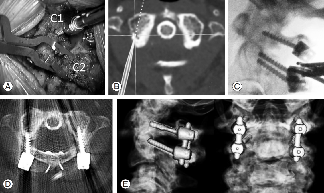
Case A5 (Table 1): atlanto-axial subluxation with pseudotumor. (A) An intraoperative photograph shows right C1 lateral mass screw (LMS) insertion during C2-direct-captured navigation. (B) The position of the lateral mass on the axial profile during C2-direct-captured navigation can be confirmed, (C) but C1 LMS needs to be monitored not to go over C1 posterior arch from the sagittal plane of fluoroscopy. (D) Postoperative axial computed tomography (CT) profile shows C1 LMS of both sides, autologous iliac bone, and sublaminal wiring. (E) Three-dimensional CT images show C1 LMS-C2 pedicle screw-rod posterior fusion.
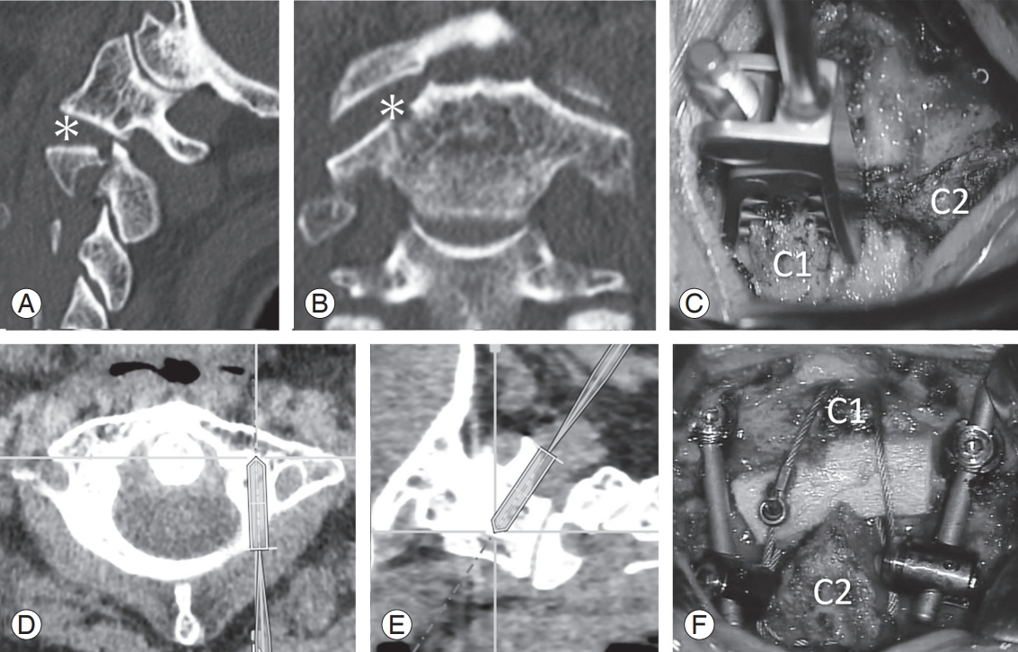
Case B5 (Table 1): C2 traumatic spondylolisthesis type I. Right sagittal (A) and coronal computed tomography (CT) profiles (B) show longitudinal fracture of the right C2 pedicle and a disrupted right C1–C2 facet (*). We chose C1–C2 posterior fixation. Because the left transverse canal showed high-riding, bilateral C2 laminar screws were selected for the anchor of C2. (C) Panel C shows a photograph of the spine clamp with a spine tracker attached to the C1 posterior arch. The axial (D) and sagittal CT profiles (E) show virtual trajectories of the left C1 lateral mass screw. (F) Panel F shows the final operative image.
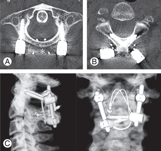
Case B5 (Table 1): 1 year after surgery. (A) Axial computed tomography (CT) profile shows C1 lateral mass screw of both sides and iliac bone (*). (B) Axial CT profile reveals C2 translaminar screw inserted without interfering with each other and in a cross into the C2 lamina. (C) Three-dimensional CT images show C1–C2 posterior fusion.
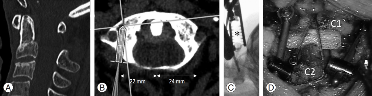
Case B6 (Table 1). The patient had a C1 bony anomaly. (A) Sagittal computed tomography (CT) image reveals C2 odontoid fracture type III. (B) The axial CT profile shows the virtual trajectory of the right C1 lateral mass screw (LMS). The distance from the C1 posterior tubercle to the predicted insertion point of LMS is asymmetric, 22 mm on the right and 24 mm on the left side. A lateral fluorograph shows C1 LMS under navigation. (C) Note that the spinal clamp (*) holds the C1 posterior arch steadily. (D) Panel D shows the final operative image.
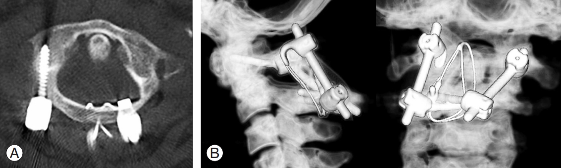
Case B6 (Table 1): 1 year after surgery. (A) The axial computed tomography (CT) profile of the C1 level demonstrates right lateral mass screw and the hook hung on the left posterior arch. (B) The three-dimensional CT images show C1–C2 posterior bone fusion.
3. Results section
In group A, the average operating time was 207 minutes (range, 163–237 minutes), and in group B, it was 173 minutes (range, 145–212 minutes). The average estimated blood loss in group A was 108 mL (range, 5–310 mL) and 61 mL (range, 5–224 mL) in group B. All patients were able to walk upon discharge, and the average length of hospital stays, including a stay in the rehabilitation department for convalescence, was 49 days (range, 9–114 days) for group B, and 27 days (range, 14–62 days) for group A. The mean follow-up periods after surgery were 46 months in group A and 15 months in group B. After the C1–C2 posterior fusion, all patients had osseous bone fusion, as seen on a CT scan over 6 months (Figs. 1E, 3C, 5B). Postoperative CT images of the cervical spine revealed that all screws had been placed as planned, except one C1 LMS in group A with a breach of the cortex on the side of the spinal canal. In group B, there were no screw placement issues, and none of the patients experienced any postoperative problems including epidural hematomas, vertebral artery injuries, or cerebrospinal fluid leaking. A nonparametric Mann-Whitney U test was used to evaluate the estimated blood loss and operation time and found that there was no significant difference between groups A and B. Informed consent was obtained from the patients to publish their clinical data and accompanying images.
Discussion
In cases of C1 LMS and C2 PS implantation, postoperative CT have reportedly revealed a screw breach rate ranging from 1.1% to 21% [20,21]. Several studies has explained the effectiveness of navigation in cervical spine surgery to enhance the precision of C1 LMS and C2 PS in atlantoaxial stabilization [22]. To reduce the risk of neurovascular damage during C1–C2 posterior fusion, only a small number of articles [13] have concentrated on the use of a preoperative CT-based navigation system with intraoperative C1- and C2-direct captured registration.
To ascertain the correct entry points for the C1 LMS and C2 PS/TLS and their sagittal angulation, fluoroscopy is routinely conducted on the lateral view. In fact, the overlapping jaw and teeth make it difficult to determine the degree of latero-medial angulation of the inserting screw in an anteroposterior fluoroscopic view of the C1–C2 structures. From the beginning, the insertion point of C1 LMS is determined from preoperative CT, and C1 LMS is performed by “freehand” while using fluoroscopy concomitantly to avoid damage to the vertebral artery. This is accomplished using the Goel and Laheri [5], Harms et al. [4], Tan et al. [23], and Lieut et al. [18] methods. As Tan et al. [23] described, the insertion points of LMS on the C1 posterior arch are often 19 mm distance from the C1 posterior tubercle, and the insertion angle is directed slightly medial from 0° to 15° [5,18,24]. In our series, the insertion location of the C1 LMS is also presumptively always 19 mm laterally from the middle of the C1 posterior arch [24]. The point corresponds to the transposition that starts from the lateral mass to the posterior arch [17]. The preoperative CT examination of the C1 LMS trajectory is essential because there are exceptions like group B6. The intraoperative C1- and C2-direct captured registration and preoperative CT-based navigation system enable the surgeon to simultaneously evaluate the screw’s trajectories on the axial, sagittal, and coronal planes (lateromedial and craniocaudal trajectories for C1 and C2 screws). This is in contrast to fluoroscopy. As a result, we discovered that as well as with intraoperative CT navigation, the preoperative CT-based navigation system with intraoperative individual vertebral registration is superior to intraoperative fluoroscopy guidance alone. The images of preoperative CT-based navigation generated by multidetector helical CT are high definition in the axial, sagittal, and coronal planes as well as three-dimensional reconstruction images, in contrast to an intraoperative navigation system like the O-arm system. Because it is challenging to attach a spine clamp-tracker steadily to the C1 posterior arch, the clamp is frequently attached to the C2 spinous process or the Mayfield head holder outside of the surgical field [13]. The preoperative CT data collected with the patient in the supine position may not match the intervertebral anatomic relationships with the patient in the prone position during surgery. This discrepancy has led to fatal navigation errors. During C2-direct-captured navigation, the position of the transverse foramen and lateral mass on the axial profile can be established, but C1 LMS needs to be watched carefully so that it doesn’t cross the C1 posterior arch from the sagittal plane of fluorography. Moreover, like group B5, if there is rotating subluxation, dislocation, or lateral deviation due to C1–2 facet injury, insertion of C1 LMS in this manner may be risky. We recommend the deployment of a preoperative CT-based navigation system with intraoperative individual vertebral registration that enables the navigation of a single vertebral body at any moment to avoid this potential difference. Although attachment to the C1 posterior arch is technically achievable and a typical spinal clamp proved simple to employ in the C2 spinous process, it is unstable and unsuitable for clinical use. Stable navigation can be provided by the present model. This approach is unaffected by intraoperative changes in single vertebral anatomy following patient relocation or during surgical manipulation because we directly attach a clamp to a specific vertebral body.
The preoperative CT-based navigation with intraoperative individual vertebral registration needs attention to be used when patients with serious traumatic injuries such as C1 burst fracture and C2 traumatic spondylolisthesis type II or III have caused intravertebral instability potentially. The alignment of C1 and C2 must be determined by intraoperative fluoroscopy or intraoperative CT-based navigation system that offers real-time pictures in this case due to the high risk of intraoperative change in vertebral architecture following patient movement or during surgical manipulation.
Intraoperative CT-based navigation for atlantoaxial stabilization is not exactly available in many neurosurgical facilities. In institutions with access to the basic neuronavigation system, preoperative CT-based navigation with intraoperative C1- and C2-direct captured registration similarly offers valuable support to enhance the insertion precision of C1 LMS and C2 PS/TLS, if any. There was no malposition of screws in group B and no postoperative complications in all patients.
Notes
No potential conflict of interest relevant to this article was reported.
Author Contributions
Conceptualization: YI; data curation: YI, RK, SN, KY, OY, IA, JS, TO, HY; formal analysis: YI, RK, SN; funding acquisition: SW, KW; methodology: YI; project administration: YI, SW, KW; visualization: YI; writing–original draft: YI; writing review & editing: YI, KM; and final approval of the manuscript: all authors.
Acknowledgements
We are grateful to Ms. Rika Sueyoshi and Mr. Takuya Sano for their excellent operation of navigation system.