Sagittal Radiographic Parameters of the Spine in Three Physiological Postures Characterized Using a Slot Scanner and Their Potential Implications on Spinal Weight-Bearing Properties
Article information
Abstract
Study Design
Prospective radiographic comparative study.
Purpose
To compare and understand the load-bearing properties of each functional spinal unit (FSU) using three commonly assumed, physiological, spinal postures, namely, the flexed (slump sitting), erect (standing) and extended (backward bending) postures.
Overview of Literature
Sagittal spinal alignment is posture-dependent and influences the load-bearing properties of the spine. The routine placement of intervertebral cages “as anterior as possible” to correct deformity may compromise the load-bearing capabilities of the spine, leading to complications.
Methods
We recruited young patients with nonspecific low back pain for <3 months, who were otherwise healthy. Each patient had EOS images taken in the flexed, erect and extended positions, in random order, as well as magnetic resonance imaging to assess for disk degeneration. Angular and disk height measurements were performed and compared in all three postures using paired t-tests. Changes in disk height relative to the erect posture were caclulated to determine the alignment-specific load-bearing area of each FSU.
Results
Eighty-three patients (415 lumbar intervertebral disks) were studied. Significant alignment changes were found between all three postures at L1/2, and only between erect and flexion at the other FSUs. Disk height measurements showed that the neutral axis of the spine, marked by zones where disk heights did not change, varied between postures and was level specific. The load-bearing areas were also found to be more anterior in flexion and more posterior in extension, with the erect spine resembling the extended spine to a greater extent.
Conclusions
Load-bearing areas of the lumbar spine are sagittal alignment-specific and level-specific. This may imply that, depending on the surgical realignment strategy, attention should be paid not just to placing an intervertebral cage “as anterior as possible” for generating lordosis, but also on optimizing load-bearing in the lumbar spine.
Introduction
The human spine is a highly mobile load-bearing column. Its sagittal alignment comprises self-adjusting reciprocal curves [1] that constantly try to maintain balance, so as to achieve energy conservation [2] and good health-related quality of life scores [3]. Although spinal alignment is well documented in standing, it is far less well studied across other commonly assumed physiological postures [4]: in particular, the slump sitting flexion that gives the maximum kyphosis [5] and the backward bending extension that gives the maximum lordosis [4]. Since spinal alignment changes most when adapting between these different postures, it is expected that the load-bearing properties of the axial skeleton will also vary between them.
The lumbar spine’s load-bearing area lies largely within its anterior column throughout most of its range of movement [6] and can be represented by changes in relative disk heights across the endplates [7,8]. In this study, we aimed to identify the load-bearing pattern of each functional spinal unit (FSU) using the changes in relative disk heights that occur during commonly assumed, clinically meaningful physiological postures: flexion (slump sitting), erect (standing), and extension (backward bending). The results can potentially serve as an additional guide for intervertebral cage placement to achieve spinal realignment while respecting the strut properties of cages. Additionally, it may also lend some insight into the mechanical reasons for catastrophic hardware failure, such as rod breakages, after spinal deformity surgeries.
Materials and Methods
1. Study design
This was a radiographic comparative study of prospectively collected data from a single, academic, tertiary, healthcare center. Prior to study commencement, ethics approval was obtained from the local institutional review board (2018/00982) under the National Healthcare Group with waiver of consent. No sources of funding were required for this study, and there are no conflicts of interest to be declared.
2. Patient cohort
This study included consecutive patients aged 18–25 who presented to the spine outpatient clinic with nonspecific low back pain lasting less than 3 months. The study enrolment period was over a randomly selected, consecutive 3-month period.
To further ensure that patients did not have spine problems that could affect their range of motion (ROM), the following exclusion criteria were set: (1) any presence of radiculopathy or neurological deficits; (2) any red-flag features suggestive of spinal trauma, infection, or malignancy; (3) any previous diagnosis of spinal conditions or interventions; (4) any spinal deformity upon Adam’s forward bending test or scoliosis (coronal curve >10°) identified on radiographs; (5) any severe pain (Visual Analog Scale >3) possibly affecting the patient’s ability to position him/herself properly for the imaging; (6) any suspected pregnancy; (7) any patients with radiographic findings of spondylolisthesis or a transitional vertebra; and (8) any patients with magnetic resonance imaging (MRI) showing Pfirrmann grade 4 and 5 disks.
These criteria were set to ensure that each FSU demonstrated reliable enough kinetics to be able to represent the position in which it might be fused, and that disk heights could be accurately measured.
3. Radiographic examination
Following clinical assessment, all patients underwent imaging taken in three frequently assumed, physiological postures in a randomized order: flexed (slump sitting), erect (standing), and extended (backward bending). Images were taken using the EOS slot scanner (EOS imaging, Paris, France) under the guidance of pictorial charts and verbal instructions [9]. The three postures were performed as per previous studies in the literature [4,5]. MRI of the lumbar spine was also obtained for all patients within a month of the EOS imaging.
4. Radiographic measurements
The EOS images were reviewed using Centricity Enterprise Web ver. 3.0 (General Electric Medical Systems Information Technologies, Barrington, IL, USA) for measurements of the spinal parameters. Measurements were carried out by three blind reviewers, and an average reading was recorded. In evaluating interobserver and intraobserver variability, Cronbach’s α coefficient >0.95 was achieved for all readings.
To characterize our study cohort’s spinal alignment, the following measurements were performed on the erect EOS: sagittal vertical axis (SVA), cervical lordosis (CL), thoracic kyphosis (TK), thoracolumbar junctional angle (TL), lumbar lordosis (LL), pelvic incidence (PI), pelvic tilt (PT), and sacral slope (SS).
SVA and spinopelvic parameters were measured as per convention [10]. CL was measured using the Harrison posterior tangent method from the C2 and C7 vertebrae. TK was measured between the inferior endplate of C7 and the inferior endplate of T12. TL was taken as the angle between the superior endplate of T11 and the inferior endplate of L2. In addition, global (L1–S1) and segmental angles (L1/2, L2/3, L3/4, L4/5, and L5/S1) were measured from the flexion, erect, and extension images using the Cobb method.
For disk height measurements, each endplate was divided into four equal parts in the sagittal plane. This resulted in five separate points, starting anteriorly, at 0% (point 1), 25% (point 2), 50% (point 3), 75% (point 4), and 100% (point 5) of each endplate. Measurements were taken from the lines used to connect each same point on adjacent endplates. These measurements were performed for each lumbar intervertebral disk in all three postures. Lateral radiographs on how disk heights were measured in extension (left), erect (middle), and flexion (right) postures are shown in Fig. 1.
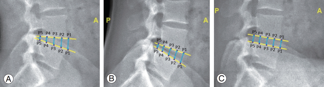
Using L4/5 as an example of how disk heights are measured in all three postures—extension (A), erect (B), and flexion (C) posture. A, anterior; P, posterior.
5. Statistical analysis
Data analysis was performed using IBM SPSS Statistics ver. 22.0 (IBM Corp., Armonk, NY, USA). The radiographic measurements for the global (L1–S1) and segmental angles, as well as the disk heights, were compared between postures using paired t-tests. Statistical significance was defined as p<0.05. Baseline characteristics and lumbar spine alignment were analyzed using a statistical significance of p<0.05. Further subgroup analyses comparing disk height measurements were subjected to Bonferroni correction directly, without a prior analysis of variance. Following the comparison between flexion–erect and erect–extension postures of five disk levels across five different points, a p<0.001 (0.05/50) level was taken as significant.
Based on the significant changes in disk heights, the sagittal alignment of each FSU from erect to flexion, and erect to extension, were then characterized. Areas of disk compression and distraction across these postures allowed the load-bearing properties of the spine to be defined. The load-bearing area in flexion and extension was plotted, and the percentage contributions of flexion and extension in relation to the erect posture at each FSU were used to plot the load-bearing area in the erect posture.
Results
Table 1 shows the baseline characteristics of the study cohort. Eighty-three patients (77 males and six females) participated in the study, and their mean age was 21.7 years. All patients had American Society of Anesthesiologists grade 1–2. The mean PI was 48.8°, and the mean LL was −35.2°. The mean SVA was −1.3 cm, and the mean PT was 16.1°. No lower limb compensation in the sagittal alignment was observed. A total of 415 disks were analyzed, of which, the majority were Pfirrmann grade 1–2 (74.7%).

Patient demographics, MRI classification of disk degeneration, and spinal radiographic parameters obtained in the erect posture
The change in mean global ROM for the lumbar spine between flexion and extension was 50.2°. Relative to the erect posture, a larger proportion of mean alignment change was found during flexion 45° (89.6%) than during extension 5.2° (10.4%) (Table 2). Therefore, the erect posture resembles the extended lumbar spine to a greater extent (Table 2). Significant differences in ROM were found between all three postures for the L1–S1 global angle and at the L1/2 segment. Significant differences were found only between flexion and erect for the L2/3, L3/4, L4/5, and L5/S1 segments. Subgroup analysis was also performed, which showed no significant differences in disk angles and disk height measurements across Pfirrmann grades and between low and high PI groups (p>0.001). Table 2 compares the measurements of the global and segmental lumbar spinal alignments, as well as the disk heights, between postures.
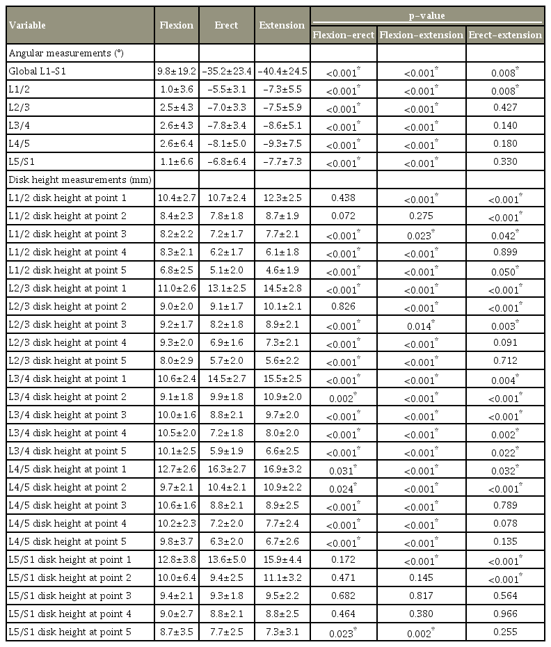
Angular alignment and disk height measurements of the lumbar spine across posture
Fig. 2 illustrates FSU dynamics and the changes in disk heights when transitioning from erect to flexion, as well as from erect to extension. These changes demonstrate portions of the disk that approximate (black arrows), separate (red arrows), or which show no change in height (green block). The portion that shows no significant change in disk height can be described as the fulcrum of movement, and represents the neutral axis. It can be determined for both flexion and extension.

Functional spinal unit dynamics and the changes in disks heights between (A) erect to flexion, and (B) erect to extension, demonstrating compression (black arrows), distraction (red arrows), and portion of the disks that showed no change in height (green block).
Fig. 3 shows the region of the spine that experiences compressive forces (represented by blue arrows) for recommending the optimal position of cages when fulfilling strut properties. Using the angular changes across postures occurring in each FSU, the load-bearing area in the erect posture is also plotted. The erect posture lies between these two common postures, albeit resembling more the extended posture, explaining why the load-bearing area plots in this posture (yellow circles) approximate the extended posture as shown in Fig. 3.

Lever dynamics from erect to flexion (A) and erect to extension (B), and their level-specific cage placement recommendations. (C) Different spinal alignments and their likely loadbearing axis. While plotted in subjects assuming different postures, it is analogous to different patients with different extents of lumbar lordosis. Plots of the load-bearing areas for each FSU in the flexed, erect and extended postures, which represent recommended cage positions for fulfilling optimal strut properties. Red circles are load-bearing areas plotted based on significant disk height changes in flexion and extension. Yellow circles were calculated using angular changes across postures occurring in each FSU to determine the load-bearing area in the erect standing posture. Sagittal spinal alignment in different postures analogous to patients with different spinal alignment. FSU, functional spinal unit.
Discussion
In recent years, the importance of restoring sagittal spinal alignment [11] has led surgeons to pursue a corrected lumbar lordosis that matches an individual’s pelvic incidence (PI–LL discrepancy) [12]. In pursuing this strategy, previous studies have advocated that intervertebral cages be placed “as anterior as possible” to maximize anterior column distraction [13-15]. However, this may have implications in terms of the cages not fulfilling their coexisting role as load-bearing struts, and potentially accounting for some of the complications seen following deformity correction surgery prior to fusion, such as pseudoarthrosis [16] and rod breakages [17].
Similar to previous studies [18,19], this study showed that the load-bearing properties of the lumbar spine change across postures, are level-specific, and are more anterior with less lumbar lordosis (Fig. 3). However, minor differences in the position of the load-bearing area were found in the current study. These could be attributed to the differences in methodology, with the current study better understanding the physiological lumbar spine alignments, i.e., using flexed (slump sitting), erect (standing), and extended (backward bending) postures, which gives greater clinical relevance to spinal realignment surgeries. This study uses different postures and their associated different alignments in each individual to conclude the relationship between load-bearing properties and spinal shape. Its methodology removes any interindividual confounding factors, thus achieving proof-of-concept. Its extrapolation to recommendation of cage placement across individuals, though logical, should still be tested in future studies.
Along with other studies [18,19], the current study also supports the notion that cage placement should be influenced by the final shape in which the lumbar spine is fused. While respecting the advantages of “as anterior as possible” cage placement for lordosis realignment, a mechanically more stable anterior column reconstruction from cage placement may be preferred. This includes situations when the lumbar spine is required to be fused in lordoses of varying magnitudes (over- and undercorrection strategies [20-22]) and curve shapes (restoring Roussouly curve type strategies [1]).
Various alignment targets for the lumbar spine have been proposed in the literature [23,24]. To date, there is ambiguity as to what an ideal spinal alignment entails, as different surgeons strive to fuse the lumbar spine in different degrees of lordosis. In accordance with the SRSSchwab classification [25], which considers only the magnitude of lordotic restoration, the physiological shape of the lumbar spine is disregarded. Since a cage placed with the sole aim of maximizing lordotic restoration may not simultaneously provide optimal anterior support, as shown in our results, paying attention to the levelspecific restoration of load-bearing properties of the spine is important. Alternatively, the Roussouly classification emphasizes the need to restore individualized curve morphologies [1], and recommends that patients with type 1 sagittal profiles require shorter hyperlordotic segments in the lower lumbar spine. This implies that a larger extent of lordosis must be generated in the lower lumbar spine, urging the need to respect proper cage placement for anterior support in these segments.
Intervertebral cages, in the authors’ opinion, should be placed at least in the neutral axis, if not in the load-bearing area, to allow optimal spinal realignment and load bearing. In the event that massive lordosis is warranted in a particular FSU, the cage needs to be placed “as anterior as possible” with increased risk of rod fractures, and posterior constructs should be reinforced [26]. Alternatively, cages with reinforced anterior fixation can also be employed to improve the overall strength of the construct [27].
To fulfil optimal load-bearing properties of the lumbar spine, intervertebral cages should at least be situated on the erect weight-bearing axis, if not on the load-bearing area. Fig. 3 illustrates a snapshot of the plotted loadbearing areas at each lumbar intervertebral level in different alignments and recommends ideal, level-specific cage positions, assuming fusion is performed in these FSU alignments. Awareness of the varying load-bearing areas occurring in different extents of lumbar lordosis can help surgeons achieve their desired amount of correction while minimizing complications. As determined in this study, this position is more anterior in a less lordotic FSU, and more posterior in a more lordotic FSU (Fig. 3). For example, L1/2 will require the furthest anterior cage placement if fused in flexion, while L3/4 will require the furthest posterior cage placement if fused in the erect or extension postures. With a larger lordosis, it is also likely that facet joints may participate more in load-bearing. This is demonstrated at L3/4, where the fulcrum of movement from erect to extension is found to be posterior to the vertebral body. Therefore, we recommend that for lordotic spinal realignment in accordance to the erect posture, to optimize load-bearing function, intervertebral cages should generally be placed in the mid-zone of the endplates, or slightly posterior (Fig. 3B).
While the use of young patients with nonspecific lowerback pain, and without advanced disk degeneration, allows reliable measurement of disk heights to determine the neutral axis, and subsequently, the load-bearing area of the spine, it can be argued that the spinal dynamics of young healthy individuals may not represent those of patients with adult spinal deformity and degeneration. Nevertheless, this is offset by the fact that a realigned spine should approximate that of a normal spine, in terms of both disk height and spinal shape.
Although this method of studying spinal dynamics may differ from the conventional technique used to plot instantaneous axes of rotations (IARs) and centers of rotation (COR) in the sagittal plane, which classically compares intersecting perpendicular bisectors of the moving underlying vertebra on lateral radiographs of flexed and extended spines in the standing posture [18,28], its simplified, yet logical, methodology will allow easier understanding of the anterior column in load bearing. Further quantification of IARs to characterize COR can be performed in future studies to allow a more complete understanding of cage placement and its effect on spinal mechanics.
Conclusions
This study details disk height pattern changes in various key sagittal spinal profiles reflective of physiological loadbearing behavior. It is advantageous in demonstrating the clinically relevant, alignment-specific and level-specific nature of the load-bearing areas in the lumbar spine. It suggests that intervertebral cage placement should not be routinely “as anterior as possible,” disregarding the need to optimize load-bearing properties of the lumbar spine. However, to support its use to guide intervertebral cage placement, further clinical studies should be conducted to substantiate how the positioning of cages could affect clinical fusion rates and surgical outcomes.
Notes
No potential conflict of interest relevant to this article was reported.
Acknowledgements
We would like to acknowledge Dr. Milindu Makandura and Yu-Xiang Koh for their help in data collection.