Three-Dimensional-Printed Model-Assisted Management of Craniovertebral Junction Abnormalities: An Institutional Experience with Literature Review
Article information
Abstract
Study Design
Prospective study.
Purpose
To evaluate the utility and limitations of using three-dimensional (3D)-printed models for the management of craniovertebral (CV) junction abnormalities.
Overview of Literature
In comparison to other bony and vascular anomalies, CV junction abnormalities are difficult to treat. For cases of irreducible atlantoaxial dislocation (AAD), posterior reduction and stabilization have replaced anterior decompression as the standard management protocol. The use of 3D models, such as those described herein, can provide surgeons with in-depth knowledge of the vertebral artery course and bony anomalies associated with CV junction abnormalities.
Methods
Clinical and radiological features of 18 patients with CV junction abnormalities were analyzed between March 2017 and February 2019 at Sawai Man Singh Medical College, Jaipur, India. Dynamic computed tomography (CT) of the CV junction and CT angiographies of the neck with respect to the vertebral artery course at the C1–C2 joints were obtained and studied. Customized 3D models of the CV junction were then made based on the CT data, and rehearsal of the surgical procedure was performed using the 3D model one day prior to performing the actual procedure.
Results
Seventeen patients had congenital-type AAD, whereas one patient had posttraumatic AAD. Improvements in neck pain and myelopathy were seen in all patients at the follow-up, as analyzed using the Visual Analog Scale and the Japanese Orthopedic Association Scale score, respectively. There were no cases of malpositioning of screws or any direct vertebral artery injury, although in one patient, the distal flow in the dominant vertebral artery was cut off as it got compressed between the bony arch and the screw head.
Conclusions
Compared to computer-generated images, 3D-printed models are a more practical approach for dealing with complex CV junction abnormalities. They provide surgeons with deep insights into the complex bony anomalies as well as variations in the vertebral artery courses, thereby improving surgical outcomes.
Introduction
Craniovertebral (CV) junction abnormalities are one of the most difficult pathologies to treat and have been managed by different techniques over time. Atlantoaxial dislocation (AAD) refers to instability between the atlas and the axis (C1–C2), resulting in loss of normal articulation; this can occur in individuals all age groups but is most often seen in adolescents. The presentation of AAD may range from simple minor axial neck pain to severe disability. Approximately 50% of patients present with neck pain and restricted neck movements and 70% present with weakness and numbness [1-4]. AAD has been classified by Greenberg [5] into two subcategories: reducible and irreducible. Treatment of AAD is aimed at correcting misalignment in all planes, followed by stabilization [6-12]. The management of AAD is challenging due to its close proximity to the neural structures, vertebral artery (VA), and the associated complex bony anomalies. VA anatomy is also highly variable in this region, posing challenges during surgery. This is the first prospective study that focuses on reducing the intraoperative morbidity associated with operative techniques through the use of threedimensional (3D)-printed models to identify the exact VA course and associated bony anomalies and thus allow the planning of appropriate operative techniques with preoperative rehearsal using the model.
Materials and Methods
This study was conducted in a tertiary care institute between March 2017 and February 2019 at Sawai Man Singh Medical College, Jaipur, India. In total, 18 patients with complex CV junction abnormalities were enrolled in the study, including one patient who was known to have chronic myeloid leukemia with AAD and basilar invagination (BI). All patients were examined using digital X-rays and dynamic computed tomography (CT) of the CV junction, CT angiography of the neck vessels, and magnetic resonance imaging of the CV junction and cervical spine. 3D-assisted models of the CV junction along with VA were developed for all 18 patients, and CT angiographic images of these patients was used to extract the 3D file in surface tessellation language (STL) format. This STL file was sent to a 3D printer station for printing the model. The models were prepared using acrylonitrile butadiene styrene polymer by a fused deposition modeling printer (Fig. 1). This model provided detailed knowledge of the bony and vascular anatomy. Bony abnormalities such as occipitalized atlas os odontoideum bifid arch block vertebrae could be studied better using these models. More importantly, the VA course could be exactly delineated using the model. The surgical procedure was rehearsed on the model prior to the surgery.

(A) A three-dimensional-printed model of a patient with occipitalized atlas. (B) Lateral view of the model. (C) Practice using the model. (D) Model with occiput–C2 screws.
The preoperative clinical features and improvement in symptoms were assessed using the Japanese Orthopedic Association score (JOA score). Radiological improvement was assessed by comparing the preoperative and postoperative craniometric indices: the atlantodental interval, Chamberlain’s line, and Wackenheims clivus canal line. Dynamic flexion–extension radiographs were used to confirm the presence of irreducibility, defined as nonalignment of C1–C2 (determined on lateral CV junction radiography) after extension (neck movement) or application of cervical traction (for 48 hours). Crutchfield cervical traction was applied, starting with 7%–8% of body weight (2–5 kg depending on age and weight) in extension. The head of the bed was elevated to provide countertraction. The weight was increased every 4 hours by 0.5–1 kg, to a maximum of 12%–13% of body weight.
Patients were operated using the principle of neural decompression with stabilization of the CV junction complex. All patients in this study underwent posterior fixation with or without C1–C2 joint realignment; the operative strategy was based on whether a reducible or an irreducible dislocation was present. One patient with a reducible dislocation was treated using C1–C2 transarticular screw fixation, first described by Magerl and Seemann [13] in 1987. Occipitocervical fixation first described by Olerud et al. [14] was performed in ten patients. C1–C2 fixation was performed in the remaining seven patients, as first described by Goel and Laheri [15] and later modified by Harms and Melcher [16], who used a rod instead of a plate to connect the C1–C2 screws. In cases where the C2 pedicles were not accessible, C2 translaminar screws were inserted. C1–C2 joint realignment with a spacer or bone graft insertion and reduction of AAD and BI using the “distraction, compres- istraction, istraction, compres- compres- ompression, extension, and reduction” sequence, as described by Salunke et al. [17] and Chandra et al. [18], respectively, were performed in 11 patients (Fig. 2).
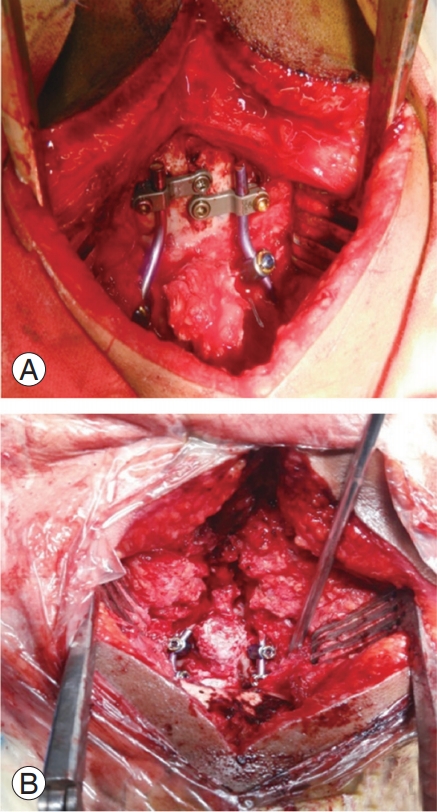
(A) An intraoperative picture showing occiput–C2 fixation. (B) Another patient with C1–C2 fixation.
Follow-up clinical and radiological evaluations were performed between 2 and 10 months postoperatively, and preoperative and postoperative JOA scores were compared. The total JOA score was used to assess motor and sensory functions of the four extremities and the sphincter, which amounted to a total of 17 points (Table 1). Follow-up X-ray and CT of the neck were performed to investigate fusion maturation and bone growth at 1–3 months, defined as bone trabeculae between the C1–C2 facets without the presence of any gap. Cystic lucencies around the implants or along the endplates and linear defects within the bridging trabeculae suggested nonfusion.

JOA Scale score
Results
Among the 18 patients in the study, 10 were male and 8 were female. The mean age of the patients was 24.7 years (range, 7–55 years). One patient had posttraumatic AAD, while the remaining 17 had congenital AAD. Anteroposterior dislocation with or without BI was observed in 16 patients and Arnold-Chiari malformation with BI was ob- -Chiari malformation with BI was ob Chiari malformation with BI was observed in two patients. Neck pain was the chief presenting complaint in 17 patients (94.4%).
Preoperative and postoperative pain was graded according to the Visual Analog Scale. Improvement in pain was categorized as mild (1–2 score), moderate (3–5), or extensive (>5) (Table 2).

Pain scale
Neck pain was present in 17 patients (94.4%), restricted neck movements were seen in 14 patients (77.7%), progressive weakness of all four limbs was present in 16 patients (88.8%), and sensory dysfunction was seen in seven patients (38.3%). Urinary incontinence/retention was present in six patients (33.3%), and dysphagia/hoarseness of voice was present in five patients (27.7%).
Irreducible AAD was seen in 12 patients (66.66%). Bony abnormalities were noted in 12 patients, including occipitalization of the atlas vertebrae in five patients (27.77%), os odontoideum in four patients (22.22%), and block vertebrae in three patients (16.66%). Anomalous VAs were seen in seven patients (38.8%).
Occipitocervical fusion was performed in 10 patients (55.55%), whereas C1–C2 fixation was performed in eight patients (44.44%). Patient characteristics along with their pre- and postoperative craniometric indices are listed in Table 3.
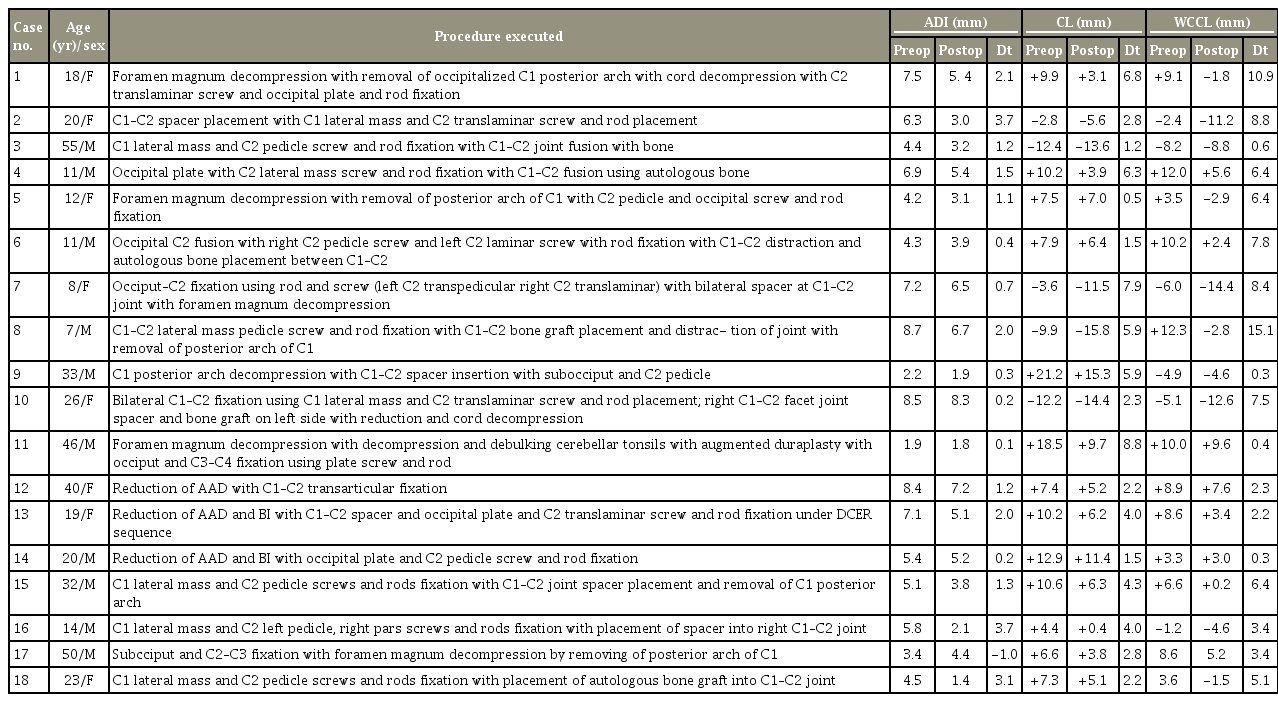
Clinical details of the 18 patients
1. Clinical improvement
Fifteen patients showed clinical improvement as evident from the assessment of their JOA scores (Fig. 3). Fusion was achieved in 15 patients at the follow-up.
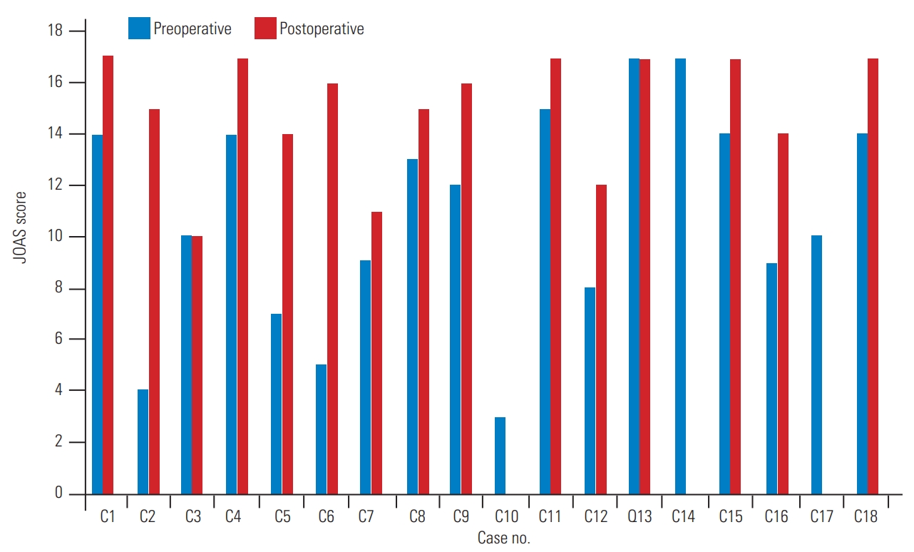
Improvement in the JOAS score. JOAS, Japanese Orthopedic Association Scale.
2. Radiological improvement
Increased atlantodental interval, when present, could be corrected in all patients as observed in the immediate postoperative scans, except for one patient in whom it increased from its preoperative state; however, there was no deterioration in the clinical profile of the patient. BI could be corrected in all patients when present (Fig. 4).
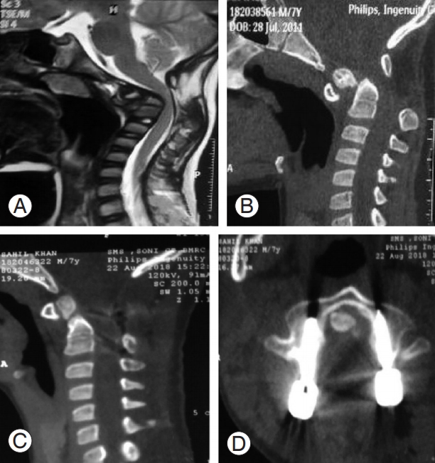
(A) Preoperative magnetic resonance imaging image showing cord compression at craniovertebral junction. (B) Preoperative CT im- Preoperative CT image showing type 1 odontoid fracture with Atlantoaxial dislocation. (C) Postoperative CT sagittal view showing good reduction. (D) Perfect alignment of C2 pedicle screws. CT, computed tomography.
3. Complications and follow-up
Case 10 left against medical advice in the postoperative period and was lost to follow-up. Case 14 died on postoperative day two; this patient did not regain spontaneous respiration in the immediate postoperative period. He was shifted to the intensive care unit and put on a ventilator. He underwent head CT (which was inconclusive) and neck CT angiography, which was suggestive of distal flow cut-off to the C2 screw in the left dominant VA. His right VA was already hypoplastic. The head CT performed on postoperative day two was suggestive of brain stem and cerebellar infarction. Case 17, a patient with chronic my- hronic myeloid leukemia, died 3 months following discharge. We did not encounter any patients with screw malposition, implant failure requiring implant removal, wound-related complications, or cerebrospinal fluid leakage.
Discussion
The atlantoaxial joint is highly mobile and unstable. Dislocation at this joint can severely compromise neural structures and the adjoining VAs. The management of irreducible AAD has seen a paradigm shift from transoral decompression followed by fixation to intraoperative joint manipulation followed by posterior fixation [19,20]. Various techniques have been employed in joint manipulation; for example, Goel’s C1–C2 joint distraction followed by placement of a spacer is a well-known technique [21]. Another technique involves C1–C2 articular facet drilling to make the joints relatively flat and normal [17]. Posterior fixation techniques have changed from sublaminar wiring to the now preferred C1 lateral mass and C2 pedicle screws or occiput–C2-based constructs, especially in cases of occipitalized C1. All such maneuvers require in-depth knowledge of the bony anomalies and variations in the VA course in patients.
Because of this intricacy, 3D-printed models have become even more important. Even the most experienced surgeons may at times find it difficult to preoperatively plan the procedure merely by looking at the radiology results. A 3D-printed model is a replica of the patient’s own CV junction anatomy, and the model can be handled and viewed from different angles, giving details regarding C1– C2 facet joint orientation, thickness of the C2 pedicle and its trajectory, VA course over the C1–C2 joint, and length of screws required.
There are several advantages with preoperative rehearsal using 3D-printed models. The incidence of C2 screw malposition with breach of the C2 VA groove as reported in the literature can be as high as 8% [22]. Using the 3D-printed models in this study, there was no malpositioning of screws. Guo et al. [23] similarly found a higher acceptable screw placement rate of 94.6% in the group in which 3D model-based navigation templates were used, compared to a 70.27% acceptable rate in the control group in which screws were fixed using fluoroscopy. Yang et al. [24] found that overall screw positions were incorrect in 32.9% of group A patients treated with conventional free-hand techniques, compared to 11.3% in group B patients who were treated with internal fixation assisted by 3D-printed models.
Wright and Lauryssen [25] reported that VA injury can be as high as 4.1% per patient or 2.2% per screw inserted. Here, using 3D-printed models, no cases of direct VA injury with torrential intraoperative bleeds were observed, but in one patient, the distal flow in the dominant VA was cut off as the vessel got compressed between the screw head (tulip) and the bony arch. This highlights the importance of careful soft tissue dissection and mobilization of the artery, especially in cases where VA has a medial loop over the C1–C2 joint [17]. If it is not possible to adequately mobilize the vessel loop, it is better to change the strategy from using transpedicular to translaminar screws.
Occipital squamous bone is the thickest in the midline in both the outer and inner table for occipital plate screw fixation. In one of the patients in this study, however, occipital keel thickness did not coincide with the midline thickness of the inner table; this could only be identified using the 3D-printed model; hence, an oblique trajectory had to be used to fix the occipital plate screws, precluding any possible injury to the occipital sinus and cerebellum.
Preoperative rehearsal also helped in determining the best possible method for posterior fixation according to the bony abnormalities that were present and the variations in the vascular anatomy in the patients. The clinical and radiological improvements seen in this study are comparable to those seen in other studies [17,26]. Goel et al. [27] concluded that 3D-printed models can improve surgical planning, enhance diagnostic quality, assist in preoperative simulation, and emerge as a primary investigational method at the very least for complex CV junction abnormalities.
Despite these advantages, the use of 3D-printed models still has limitations. One major disadvantage of 3Dprinted models is the absence of soft tissues in the model; because of this, preoperative rehearsal pertaining to tissue dissection and mobilization cannot be performed. Another important drawback is that any floating bone segments do not get printed, as printing involves deposition of small beads one upon the other in 3D space; hence, one should be prepared to deal with such unexpected abnormalities intraoperatively (as found in one of the patients in this study).
Conclusions
In summary, 3D-printed models are extremely helpful to neurosurgeons as they can be held, rotated, and visualized from different angles, helping them better understand complex CV junction abnormalities. Practice using the model makes the surgeon more confident during the surgery because they become more familiar with the important surgical landmarks. We have also found them to be superior to cadaveric dissection, as cadavers may not have the same set of abnormalities as the patient being operated on. In our experience, these models should be included as a basic investigation tool in patients with CV junction abnormalities.
Notes
No potential conflict of interest relevant to this article was reported.
Author Contributions
All authors participated in clinical assessment, management of the patient, and preparation of the manuscript. The manuscript has been read and approved by all authors, and each author believes that the manuscript represents honest work.