Mid-length Pedicle Screws in Posterior Instrumentation of Scoliosis
Article information
Abstract
Study Design
Prospective analysis of collected data.
Purpose
We determine the need for the use of mid-length pedicle screws (screws with 2.5-mm long increments) during posterior spinal instrumentation.
Overview of Literature
Many biomechanical studies have been performed showing that increasing the pedicle screw insertion depth provides an improved resistance to pullout, cyclic loading, and derotational forces, but no intermediate length screws were used.
Methods
We prospectively evaluated 120 patients who received posterior segmental instrumentation for structural scoliosis. Preoperatively, 91.44-cm long cassette anteroposterior (AP), lateral, and AP bending radiographs and multiplanar computed tomography were performed in all patients routinely. We measured chord length to determine the maximum probable screw length of all vertebrae. All pedicle screws were attempted to be placed as long as possible. The main intention was at least to engage the subcortical bone of the anterior vertebral cortex. Especially in the apical region, the screws were attempted to be inserted bicortically. The length, level, region, and side of each screw were recorded. Screws with 5-mm increments were called standard length screws (SLS), and middle-sized screws with 2.5-mm increments were called mid-length screws (MLS).
Results
Of 2,846 pedicle screws inserted, 1,575 (55.4%) were SLS and 1,271 (44.6%) were MLS, demonstrating a need for MLS in scoliosis surgery (p<0.05). The need for MLS increased significantly in the thoracic region, apical vertebrae, and convex side (p<0.05).
Conclusions
If anterior cortex engagement or longer placement of pedicle screws is intended during scoliosis surgery, for safer placement, screws with 2.5-mm increments should be available in posterior instrumentation systems.
Introduction
Pedicle screw fixation has become a widely used instrumentation technique in spinal surgery since it has been popularized by Roy-Camille et al. [1]. With its stronger biomechanical properties, pedicle screws enabled better three-dimensional (3D) control and shorter fusion length in scoliosis surgery [2,3].
Many biomechanical studies have shown that increasing the pedicle screw insertion depth provides improved resistance to pullout, cyclic loading, and derotational forces [4-6]. This resistance increases significantly if pedicle screws are inserted deep enough to engage the anterior vertebral cortex [5-7]. Clinically, bicortical pedicle screws have been used in spondylolisthesis surgery [8]. However, anterior cortex penetration is controversial in the thoracic region because of potential visceral organ or vascular injury [9]. On the other hand, techniques have been described to insert pedicle screws more accurately and be close to the anterior vertebral cortex using fluoroscopy or stereotactic navigation [10-12].
To make an effective direct vertebral rotation (DVR) and prevent pullout in our adolescent patients with idiopathic scoliosis, we aimed to insert pedicle screws that were as long as possible, using the whole chord length. If possible, we performed intentional anterior cortex penetration, especially in the apical region. We carefully engaged the anterior cortex and inserted the screw so that it was not >1 thread beyond the cortical surface. Since the visceral structures can be as near as 3–4 mm to the anterior vertebral cortex, screws with 5-mm increments would endanger them [13,14]. Therefore, we used screws with 2.5-mm increments, which we called ‘mid-length screws’ (MLS) (Table 1).

Lengths of mid-length and standard length screws
Screws with 2.5-mm increments are available in anterior but not in posterior instrumentation systems. If anterior vertebral cortex engagement is intended during posterior instrumentation, for more accurate and safe screw placement, different screw lengths in 2.5-mm increments should be available. We determined the need for the use of mid-length pedicle screws during posterior spinal instrumentation.
Materials and Methods
1. Patient demographics
We prospectively evaluated 120 patients (72 women, 48 men; average age, 19.2 years; range, 13–54 years) with structural scoliosis who received surgical correction and instrumentation between January 2012 and July 2013. The diagnoses of the patients were adolescent idiopathic scoliosis in 86 patients, congenital scoliosis in 17, adult scoliosis in 10, and neuromuscular scoliosis in seven. Patients were informed about the treatment techniques and approved the procedure. The study was done under the permission of Yeditepe University Clinic Research Ethic Committee (IRB approval no., 352).
2. Preoperative evaluation
Preoperatively, 91.44-cm long cassette anteroposterior (AP), lateral and AP bending radiographs, and multiplanar computed tomography (CT) were performed in all patients routinely to measure all vertebrae. A single observer measured the chord length on CT scans (3-mm axial sections with 1-mm overlap); and through the measurements, we could crosscheck the chord length while replacing the pedicle screws using a free hand technique (Table 2). Also, we obtained postoperative CT scans of patients to investigate for a suspected complication.

Distribution of mid-length and standard length screws according to thoracal and lumbar regions
3. Surgical procedure
All pedicle screws were inserted using a free hand technique. After a standard midline incision, the spine was exposed meticulously to the tip of the transverse processes bilaterally. Pedicle entry points were determined according to the well-known anatomic landmarks as described previously by Roy-Camille et al. [1] and Kim et al. [15]. After the presumed pedicle entry point was prepared with a rongeur, the pedicle base was entered with a sharp awl. A slightly curved, blunt-tipped pedicle finder was inserted into the pedicle and vertebral body, applying appropriate ventral pressure. With a flexible and ball-tipped pedicle sounding device, five distinct bony borders of the screw tract were palpated. The pedicle finder was advanced into the subcortical bone of the anterior cortex, where the smooth passage was stopped with resistance. With a specially designed calibrated probe (Fig. 1), the screw length was determined from the starting hole to the point where the probe touched but not perforated the anterior cortex. The nearest screw length to the measured length was chosen and the self-tapping screw was inserted slowly to maximize the viscoelastic expansion of the pedicle tract. Screws with a diameter of 5–8 mm (with 1-mm increments) were available, and the largest screws that the pedicles could accept were attempted to be inserted. If the manually tested screw insertional torque was not satisfactory, the screw was replaced with a larger one. After all screws were inserted, lateral and oblique fluoroscopic views were obtained as described previously by Krag et al. [11]. With these views, the proximity of the screws to the anterior cortex and anterior cortex penetration were evaluated. If the screw length was inappropriate due to measurement errors, it was replaced. If a screw was >1 thread beyond the anterior cortex, it was replaced with a shorter screw. If it was too short and was not engaged to subcortical bone, it was replaced with a longer screw. Special attention was given to place the screws bicortically in the apical region, particularly in the convex side.

A specially designed calibrated probe was used to precisely measure the chord length (arrow).
We performed DVR routinely, especially in rigid curves, with the Vertebral Column Manipulator device (VCM; Tasarım, İstanbul, Turkey) according to the description of Lenke. After connecting the two rods with all screw heads, the rod placed on the concave side was rotated meticulously with two rod holders. Subsequent to rotation of the concave rod, the convex side rod automatically rotated in rigid and flexible curves. Following the curve correction by 90° rod rotation, the VCM was tightened over the apex screws, at the level above and below. Neuromonitorization (motor evoked potentials) was performed throughout the procedures.
4. Measured parameters
The length, level (thoracic or lumbar), and side (convex or concave) of each implanted screw were recorded. Screws were named as MLS or standard (SLS) length screws (Table 2). The general need for MLS and particularly the need in the thoracic or lumbar regions, convex or concave sides, and apical vertebrae were calculated. Standing whole spine AP and lateral radiographs were obtained postoperatively (Fig. 2). CT was performed in some patients and we confirmed the subcortical engagement of the screws, but CT was not used routinely (Fig. 3).

(A) Postoperative radiographs of a 16-year-old girl. (B) Lateral radiograph shows the chord length effectively used at every level.
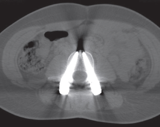
Axial computed tomography section of a lumbar vertebra showing the subcortical engagement of the pedicle screws.
In addition, we evaluated the radiographic outcomes pre- and postoperatively regarding the deformity correction (main curve and proximal and distal compensatory curve) as well as upper (UIV) and lower (LIV) instrumented vertebrae tilt, disk angle, and balance parameters (Table 3).
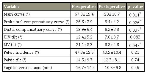
Radiological outcomes before and after the surgery
5. Statistical analysis
All statistical analyzes were conducted using IBM SPSS software ver. 21.0 for Windows (IBM Corp., Armonk, NY, USA). The χ2 test was applied to analyze the differences between thoracic and lumbar regions and convex and concave sides, and the unpaired t-test was applied to compare the alteration of apical vertebral rotation between MLS+SLS and SLS. Analysis of variance was used for the analysis and evaluation of deformity correction (main curve and proximal and distal compensatory curve) as well as UIV and LIV tilt, disk angle, and balance parameters. All p<0.05 were considered statistically significant.
Results
A total of 2,846 pedicle screws were inserted into the thoracic and lumbar vertebrae of 120 patients, including 1,575 (55.4%) SLS and 1,271 (44.6%) MLS, demonstrating a need for mid-length pedicle screws in scoliosis surgery (p<0.05).
Comparative analyzes revealed that the need for MLS was greater in the thoracic region and on the convex side (Tables 3, 4). This need increased particularly, as far as 144 apical vertebrae were concerned. Of 288 apical pedicle screws, 177 (61.5%) were MLS and 111 (38.5%) were SLS (p<0.05).

Distribution of mid-length and standard length screws according to convex and concave sides
In both groups, there were significant differences between the main curve, the proximal and distal compensatory curves, UIV tilt, and LIV tilt measurements pre- and postoperatively (p<0.05). In addition, no significant decreases were noted in pelvic incidence, pelvic tilt, and the sagittal vertical axis (p>0.05).
The grade of apical vertebral rotation was evaluated pre- and postoperatively using the Nash-Moe and Upasani methods (the percentage displacement of the convex pedicle with respect to the vertebral body width was used to approximate the angle of vertebral rotation). We compared the effects of MLS and SLS on apical vertebral derotation efficiency. MLS and SLS used in 18 patients (group 1) and SLS used in 21 (group 2) were evaluated with pre- and postoperative axial CT scans. Group 1 showed better apical vertebral derotation than group 2 (level 0, 12.9% versus 4.7%; level 1, 74.1% versus 45.3%; level II, 29.6% versus 18.1%; level IV, 46.4% versus 20.1%; p<0.05). The apical vertebral rotation showed significantly better final results in group 1 compared to group 2, and there was no pullout of any pedicle screws.
There were no intraoperative or postoperative neurovascular or visceral complications. No pullout or screw loosening occurred during the surgical procedures. Postoperative radiographs showed that all screws were of appropriate length. No screw misplacement or pedicle failure was observed.
Discussion
Scoliosis is a 3D deformity, and several techniques have been developed for its correction [16]. Use of transpedicular screws particularly with a DVR maneuver improved the transverse plane correction in scoliosis surgery. To perform the scoliosis correction maneuvers, especially DVR, more effectively and safely, a strong screw–vertebra interface (SVI) is essential [6]. Biomechanical and clinical studies have shown that pedicle screws can change their position and cause medial and lateral pedicle wall breaches during correction maneuvers [17,18]. Techniques have been described to increase SVI strength and decrease these bone failures as well as screw pullout, including pedicle screw augmentation with various cements and expandable screws [19]. Most techniques are advantageous in patients who have osteoporosis and have no value in young patients with scoliosis. Increasing the depth of pedicle screw insertion seems to be the correct choice to strengthen the SVI in these patients [6]. During DVR, with longer screws, applying the rotational force more anterior to the instantaneous axis of rotation is possible, and this ensures a greater bone–screw contact surface for better force transmission [20].
The chord length is the distance between the posterior cortical entry point of the pedicle and the anterior vertebral cortex in line with the pedicle axis [21]. This length represents the maximum length that a screw can be inserted into a pedicle. Krag et al. [4] recommended to insert pedicle screws between 80% and 100% of the chord length for optimal resistance to pullout forces. Weinstein et al. [7] documented that approximately 60% of the pedicle screw fixation strength is in the pedicle itself. The cancellous bone in the vertebral body adds another 15%–20% of strength. Placing a screw up to the anterior cortex, but not through it, can increase the strength by 16%, whereas a purchase in the anterior cortex offers another 20%–25% increase. Zindrick et al. [5] concluded that ‘through cortex’ fixation is more secure than ‘to cortex’ fixation. They showed the superiority of bicortically placed screws in pullout and cyclic loading tests. Bezer et al. [6] examined the resistance of bicortically placed screws against derotational forces and found that bicortical screws are advantageous especially on the convex side of scoliotic curves where the available screw length usually is shorter. All these studies show that the longer the pedicle screws are placed, the stronger the fixation becomes.
Many morphometric analyzes have been performed, and the chord length is variable according to age, sex, ethnic group, vertebral level, convex or concave side, and vertebral disease [21-25]. The differences in chord length may be approximately 1–2 mm between adjacent vertebrae or between convex and concave sides of one vertebra. However, the pedicle screws in posterior instrumentation systems are in 5-mm increments. Professionals generally accept that 25 or 30 mm screws are feasible from T1 to T5, 30 or 35 mm screws from T6 to T12, and 35 or 40 mm screws from L1 to L5 [25]. With these screw lengths, using the whole chord length is not possible. If longer screws are chosen, visceral structures will be in danger because these structures can be as near as 3–4 mm to the anterior vertebral cortex [13,14]. To place pedicle screws as long as possible and to engage the anterior vertebral cortex safely, screws with shorter increments are needed. Therefore, we used screws with 2.5-mm increments in our cases about scoliosis.
The amount of MLS that we used in our cases shows that there is a need for MLS if safe placement of longer pedicle screws is intended in scoliosis surgery. This amount is particularly high in the thoracic, apical, and convex regions, which may be because the chord length is shorter in the thoracic region and convex side [21-25]. More precise measurement is needed for shorter chord lengths, and this may increase the use of MLS. Another reason for more precise measurements is that we gave more attention to placing the screws bicortically in the apical region, especially in the convex side. Instrumentation of the apical vertebrae is of critical importance in terms of better derotation results in the DVR technique Therefore, screws at this region should be sufficiently long enough to produce an effective derotational torque. Furthermore, if apical screws on the convex side cannot be inserted in an ideal direction and length due to rib hump deformity, bicortical placement increases the derotational forces that can be applied at this region [6]. Therefore, we placed the screws bicortically on the convex side of the apical region.
Clinically, bicortical fixation through the anterior cortex parallel to the S1 endplate has been used successfully in spondylolisthesis surgery [8]. On the contrary, advancement of pedicle screws beyond the anterior vertebral cortex is not a well-accepted technique in the thoracic and lumbar regions, due to potential visceral organ or vascular injury [9]. In scoliosis surgery, the incidence of visceral injury, including pulmonary complications, is approximately 1%–2% [26]. Cases have described of removal of pedicle screws due to potential complications [27], but a recent systematic review reported no major vascular complications seen during scoliosis surgery [28]. Upendra et al. [29] classified minimal (2 mm) anterior wall perforations as unacceptable, but emphasized that these perforations did not cause neurovascular complications. Researchers previously have shown that the structures that could be damaged after placement of the pedicle screws (on the left side aorta, esophagus; on the right side, azygos vein, inferior vena cava, intercostal veins, and ductus thoracicus) are 4 mm away from the nearest vertebral part.
Moreover, in all of these examples, the anterior cortex was penetrated unintentionally. If the anterior cortex is engaged carefully and the screw is inserted with the tip that is not >1 thread beyond the cortical surface, then structures anterior to the vertebral body will not be in danger. With careful probing, precise measurement, and appropriate fluoroscopic views, we were able to insert the screws without any neurovascular or visceral complications. To perform more precise measurements, especially measuring the rotation of the apical vertebrae, and make the procedure safer, preoperative CT and intraoperative stereotactic navigation can be used, but intraoperative CT scanning and stereotactic navigation are an expensive setup that can be found only at selected centers. Thinking worldwide, few hospitals have this opportunity. Also, standard post- or preoperative CT scanning for a patient without a complication or suspected complication to evaluate pedicle screw lengths is not ethical, because of extra radiation exposure. We only obtained postoperative CT scans in 16 patients which we needed to investigate for a suspected complication. These limited CT scans showed us that we managed to purchase maximum length pedicle screws with our technique.
One limitation of our study is that we did not evaluate the factors that can affect SVI strength other than screw length. As known, the biomechanical fixation strength of pedicle screw instrumentation depends on many factors, most importantly bone mineral density (BMD) [30]. We did not measure the BMD in our study. However, most of our patients were young and had good bone quality. We determined the screw diameter by manually testing the screw insertional torque, which was a subjective evaluation. However, we did not observe any pullout episodes in our cases. Another limitation may be that we did not create a cost analysis. Extra screw inventory certainly will increase manufacturing costs, and its effect on hospital costs should be analyzed. The final limitation of this study is the lack of clinical results showing that precise engagement of the anterior vertebral body cortex improves outcomes. This may be a topic of another study that compares the outcomes of SLS and MLS constructs.
Conclusions
To our knowledge, pedicle screws with 2.5-mm increments are not used routinely in posterior instrumentation systems, and this is the first study to evaluate the need for MLS in posterior spinal instrumentation. With a proper technique, longer screws can be placed safely using the chord length as much as possible. To do this, screws with 2.5-mm increments are necessary and they should be available in posterior instrumentation systems. Randomized clinical trials, in which cases with and without anterior cortex purchases are compared, would further shed light on this issue.
Notes
No potential conflict of interest relevant to this article was reported.