


Introduction
The sacral alar iliac (SAI) screw technique has been introduced and popularized by OŌĆÖBrien et al. [1]. Nowadays, SAI screws are applied in a variety of clinical settings. The SAI screw utilizes the sacral alar trajectory screw and is placed across the sacroiliac (SI) joint into the ilium [1ŌĆō4]. Several authors have already reported that the SAI screw technique can minimize the implant prominence and soft tissue dissection [5ŌĆō7]. Additionally, the SAI screw can be placed through percutaneous and minimally invasive methods [8,9]. OŌĆÖBrien et al. [1] reported the mean length of the SAI screw and the mean angle of the trajectory in the lateral and caudal directions in Caucasian cadavers subject to the condition that the entry point was 1 mm inferior and 1 mm lateral to the foramen at S1. Chang et al. [5] reported that the mean starting point in S2 was 25 mm caudal to the superior endplate of S1 and 22 mm lateral to the sacral midline based on the ideal trajectory in the computed tomography (CT) radiographic analysis of Caucasians. Zhu et al. [6] reported the mean length of the SAI screw and the mean angle of the trajectory subject to the condition that entry point was 1 mm inferior and 1 mm lateral to S1 foramen in CT radiographic analysis of Chinese. In these reports, the most commonly used entry point was 1 mm inferior and 1 mm lateral to the foramen at S1. Trajectories and lengths of the SAI screw are based on these predecided entry points. To our knowledge, there is no detailed three-dimensional (3D) imaging study on the ideal entry point of the SAI screw. Thus, in this study, we used a 3D medical image processing software for a more detailed investigation. Although the dorsal neural foramen at S1 is a landmark on the sacrum for SAI screw insertion, nerve root damage during the insertion of SAI screws remains to be a general concern. Thus, this study aimed to clarify the ideal entry point and trajectory of SAI screw in relationship with the dorsal foramen and nerve root at S1.
Materials and Methods
This study was performed according to the principles described in the Declaration of Helsinki and was approved by the Institutional Ethics Review Board of Okayama University Hospital (approval no., 1702ŌĆō007). We applied an opt-out method to obtain consent on this study because this was a retrospective study and analysis used anonymous clinical data which were obtained after each patient agreed to surgical treatment according to written consent.
1. Subjects
Preoperative CT data for adult spinal deformity from 32 patients were used. In total, 13 males and 19 females were examined. The average age of males and females were 59.7 years and 61.5 years, respectively, at the time of the CT examination. The average height and weight were 161.8 cm and 63.7 kg in males and 148.8 cm and 47.5 kg in females, respectively. No patient had metabolic bone disease, previous history of pelvic fracture, or pelvic surgery.
2. Computed tomography reconstruction and radiographic parameters
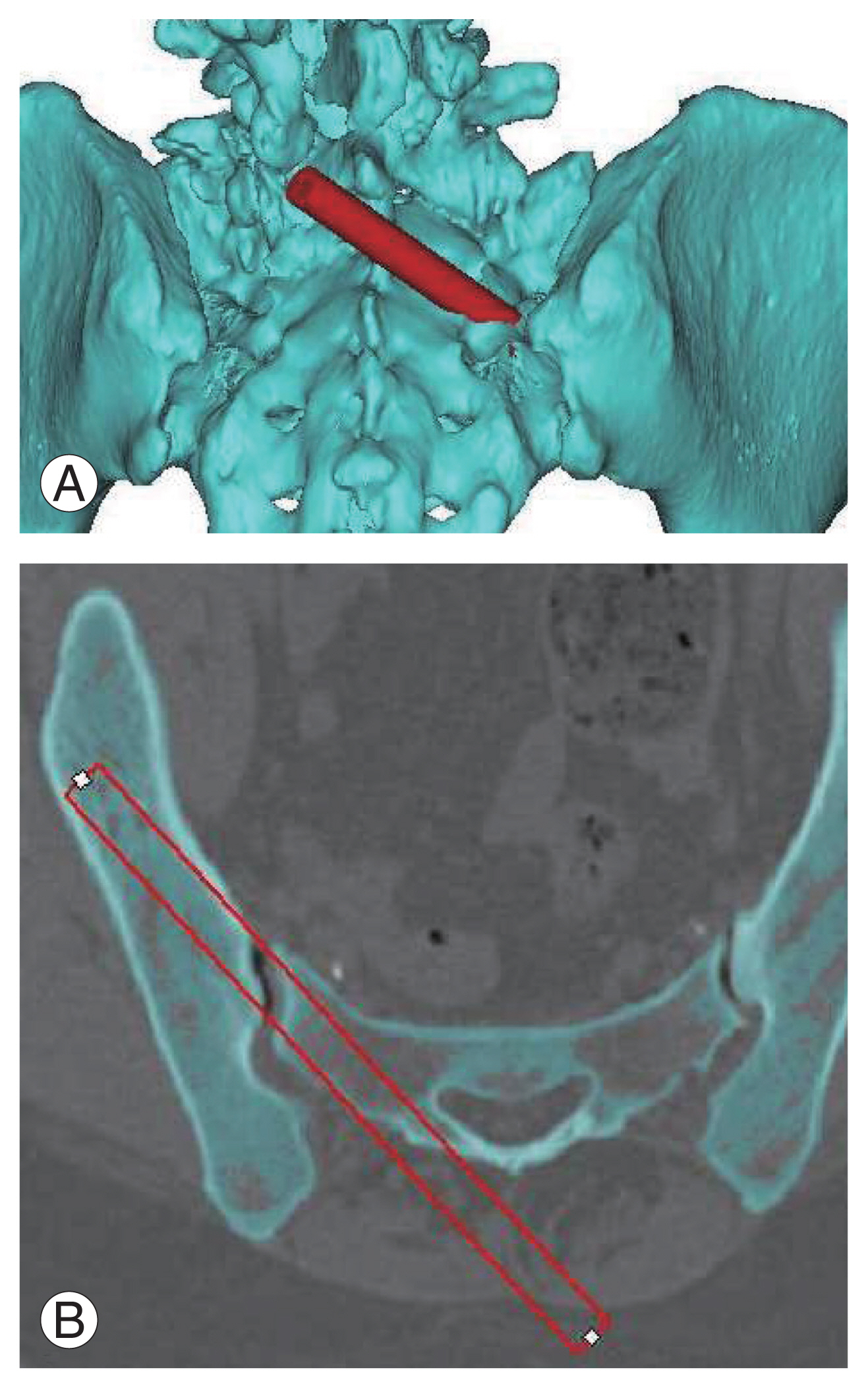
A 64-slice CT scanner (Siemens Healthineers, Erlangen, Germany) was used to scan the entire pelvis with a layer thickness of 1 mm. The CT scan data (Digital Image Communications in Medicine format) of each patient was imported into the software Mimics (ver. 17.0; Materialise, Leuven, Belgium) for a 3D interactive viewing and manipulation. The threshold Hounsfield unit value needed to create a bone model was set at ŌĆ£226 to maximum.ŌĆØ After the 3D digital image was reconstructed, virtual cylinders (diameters of 8 mm, 9 mm, and 10 mm) were drawn to mimic the SAI screws inserted from the right sacrum to the right ilium (Fig. 1). In this study, the SAI screw was placed in such a way to penetrate the SI joint without violating the cortex. Furthermore, its tip was designed to be localized at the supra-acetabular region without causing damage to the contralateral cortex.
We then assessed the maximum length of SAI screws with diameters equal to 8 mm, 9 mm, and 10 mm. We also measured the trajectories of the SAI screws with these maximum lengths in the transverse and sagittal planes and distance between the entry point of the longest SAI screw and the posterior foramen at S1.
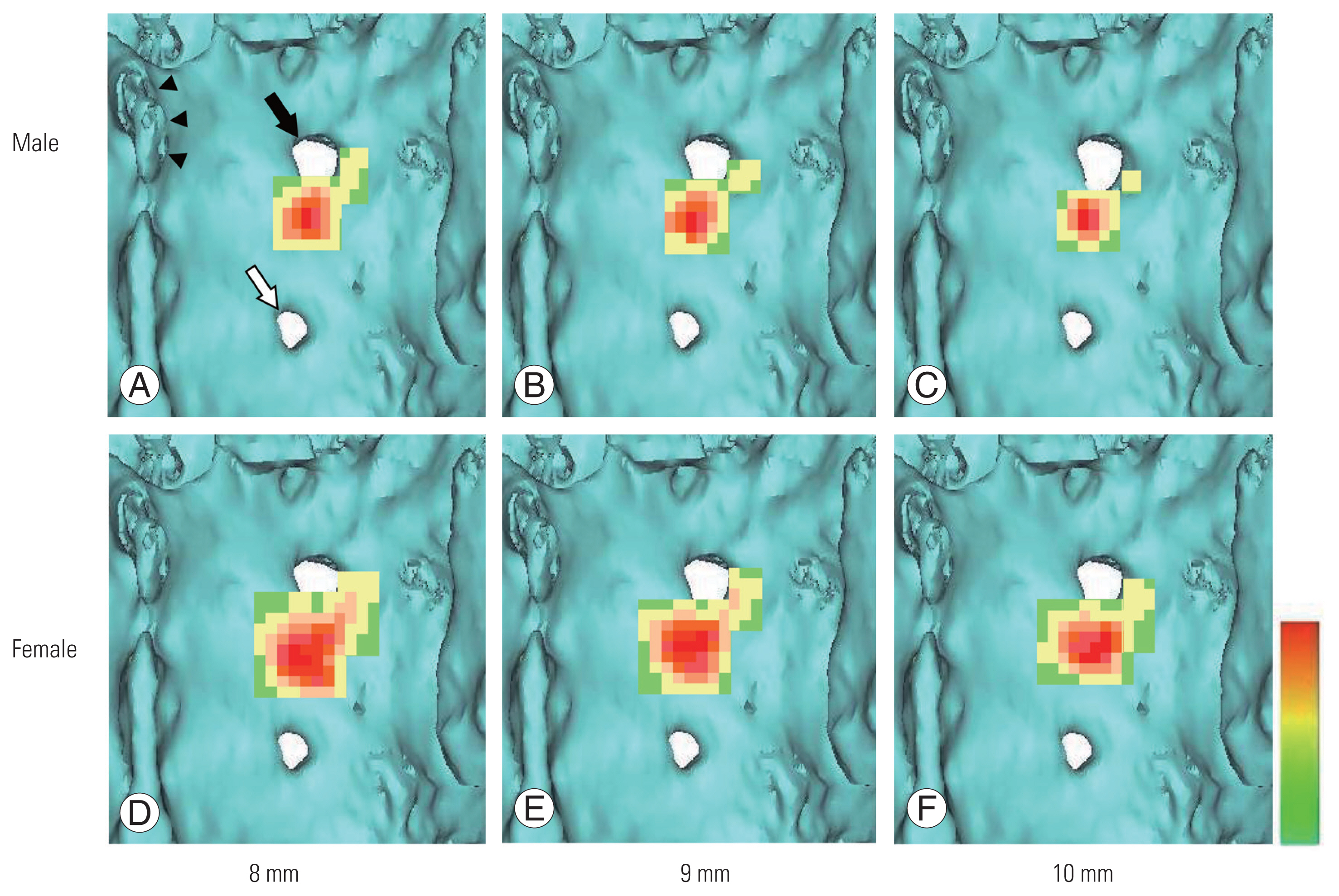
To assess the ideal entry point of SAI, we opted to apply a color mapping method on the surface of the sacrum. Firstly, we created a virtual grid spacing of 2.5 mm at the origin at the center of the S1 posterior foramen. Secondly, we applied virtual screws with various lengths from each grid intersection. We then allocated the following point grades when the virtual screw remained within the bone depending on the screw length: 5 points, maximum length; 3 points, maximum minus 5 mm; and 1 point, maximum minus 10 mm length. Each square comprised 4 quadrants and was scored with the average point of 4 entry points. We repeated this measurement and summed the square points of all patients. Lastly, we created a color mapping on the surface of the sacrum depending on the screw size (8 mm, 9 mm, and 10 mm). The calculation of color mapping was made automatically using Excel 2013 (Microsoft Corp., Redmond, WA, USA), with red denoting the maximum and green the minimum.
3. Relationship between S1 nerve root and the dorsal foramen
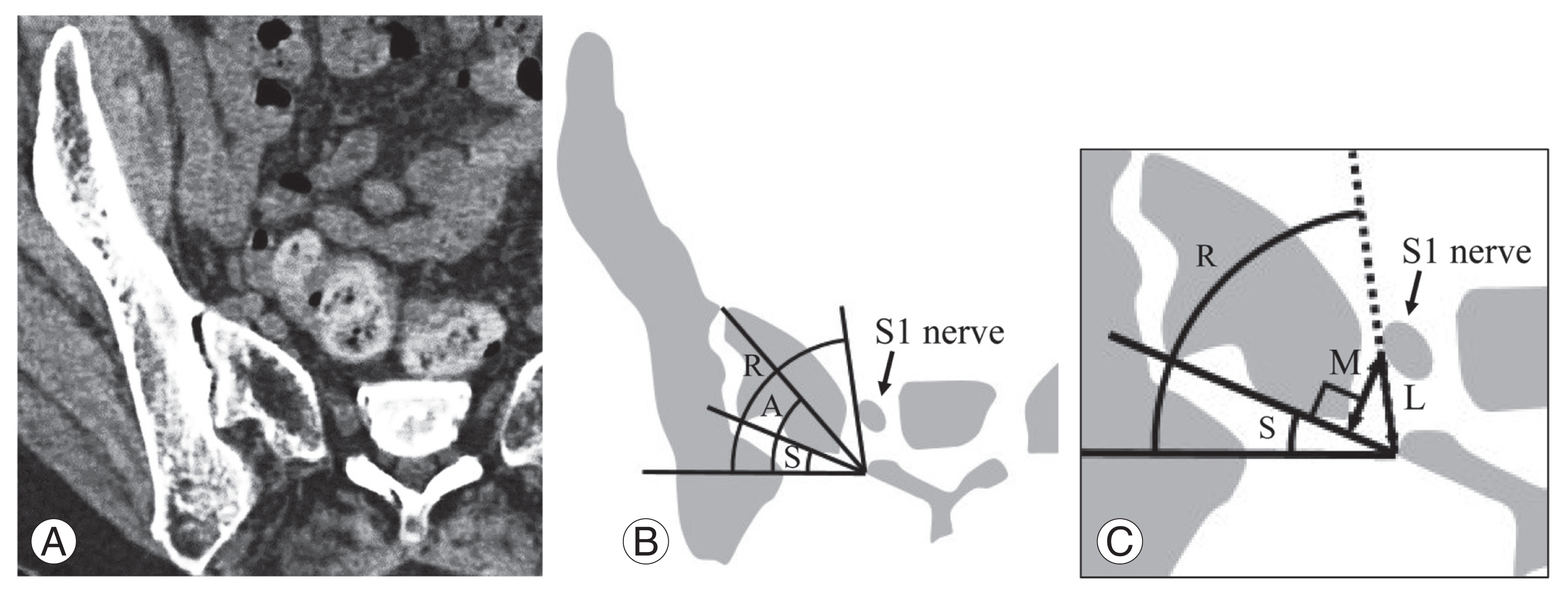
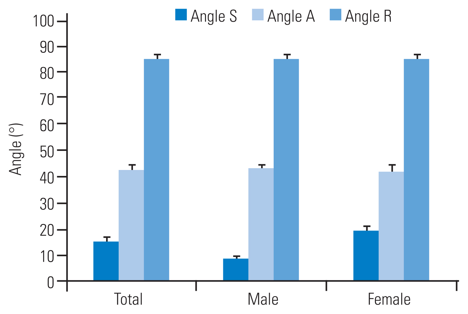
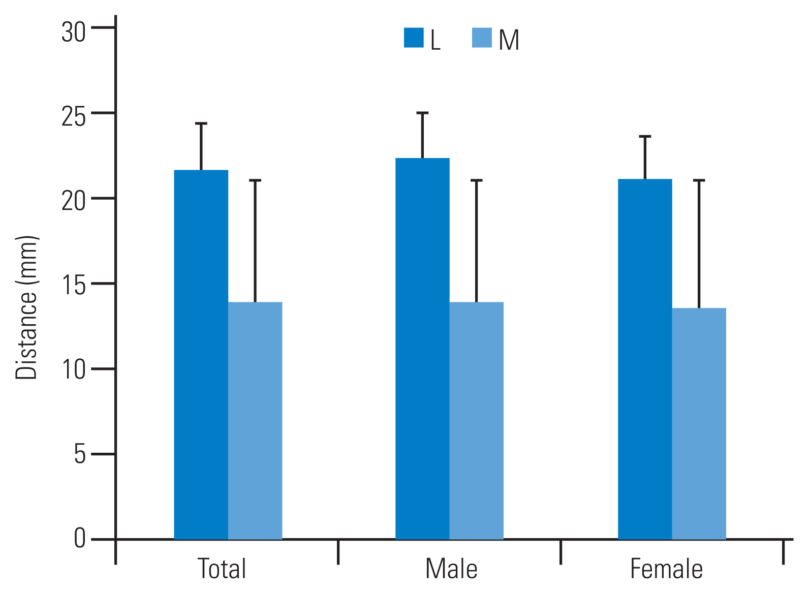
To analyze the relationship between the nerve root at S1 and the dorsal foramen, we selected the axial CT slice, in which the neural foramen at S1 appeared to have the largest width. We then defined the following three angles: angle S, an angle between a horizontal line and a tangential line of the foramen at S1; angle A, an angle between a horizontal line and a line connecting the medial edge of the foramen at S1 and the alar; and angle R, angle between a horizontal line and a line connecting the medial edge of the foramen at S1 and the lateral edge of the nerve root at S1 (Fig. 2). We measured the distance from the dorsal medial edge of the foramen to the nerve root (L) at S1 and the distance from sacral surface to the nerve root (M) at S1 as L├Śsin (R-S) (Fig. 2B). All results were represented as mean and standard deviation (SD).
Results
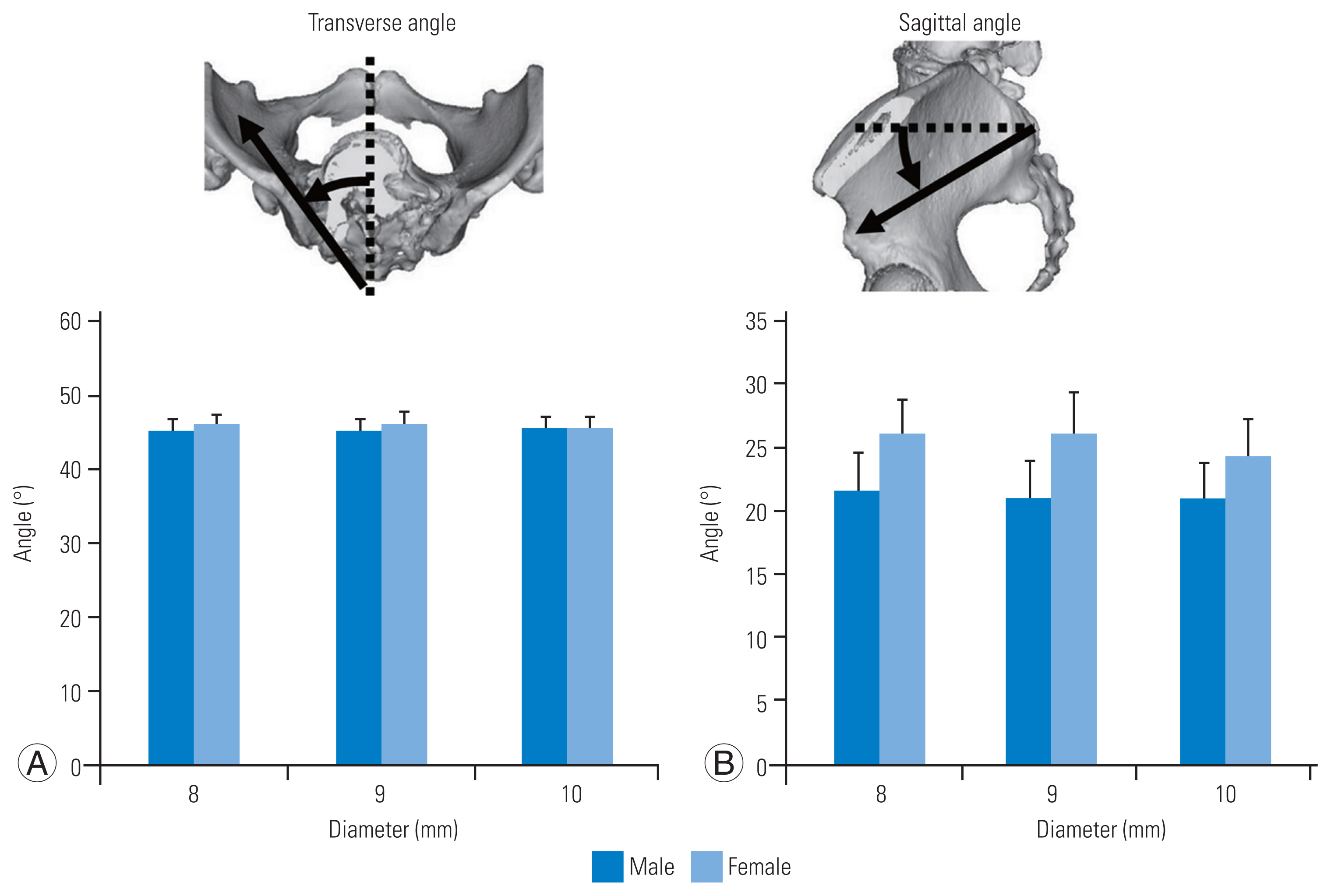
The mean┬▒SD maximum lengths of SAI screws with diameters of 8 mm, 9 mm, and 10 mm were 122.1┬▒2.4 mm, 118.9┬▒2.8 mm, and 116.6┬▒3.0 mm in males and 112.1┬▒3.4 mm, 105.8┬▒3.7 mm, and 103.9┬▒4.6 mm in females, respectively. The trajectories of the longest SAI screw are shown in Fig. 3. The mean┬▒SD angles in the transverse plane with diameters equal to 8 mm, 9 mm, and 10 mm in males were 45.2┬░┬▒1.7┬░, 45.4┬░┬▒1.6┬░, and 45.6┬░┬▒1.6┬░, respectively; meanwhile, those in females were 45.9┬░┬▒1.6┬░, 46.1┬░┬▒1.8┬░, and 45.6┬░┬▒1.7┬░, respectively. The mean┬▒SD angles in the sagittal plane with diameters of 8 mm, 9 mm, and 10 mm in males were 21.7┬░┬▒3.0┬░, 21.1┬░┬▒2.8┬░, and 20.8┬░┬▒2.9┬░, respectively. Moreover, those in females were 26.0┬░┬▒2.9┬░, 26.1┬░┬▒3.1┬░, and 24.2┬░┬▒3.1┬░, respectively. These results indicate that the mean trajectory in females was more lateral in the transverse plane and more caudal in the sagittal plane than those in males.
The entry points of the longest SAI screws were located medially and caudally to the posterior foramen at S1 in all cases. The mean distances of the entry points of the longest SAI screws with diameter of 8 mm, 9 mm, and 10 mm from the posterior foramen at S1 were 6.9 mm, 5.5 mm, and 4.1 mm in the medial direction and 2.8 mm, 2.6 mm, and 2.6 mm in the caudal direction in males, respectively. Those in females were 5.0 mm, 4.4 mm, and 3.9 mm in the medial direction and 1.8 mm, 2.1 mm, and 2.5 mm in the caudal direction, respectively. Color mapping results showed that high scored areas are located medially and caudally to the posterior foramen at S1 in all diameters (Fig. 4). The means of the angles S, A, and R were 20.9┬░, 56.4┬░, and 93.5┬░, respectively (Fig. 5). The means L and M were 21.8 mm and 13.9 mm, respectively (Fig. 6).
Discussion
Pelvic fixation has been commonly used to correct severe scoliosis and/or kyphosis observed in patients with various neuromuscular conditions and adult spinal deformity [10,11]. However, long spinal fusion to the sacrum is still a challenging procedure. Traditional pelvic fixations include Galveston, sacral, and iliac screw techniques [12ŌĆō16]. These conventional techniques have several problems related to their biomechanical strengths and implant prominence [15,17ŌĆō20]. The Galveston technique is one of the most popular methods, but this often requires complex and 3D rod bending. However, compared with the Galveston technique, the combined technique using sacral and iliac screws allows easier implant placements [17,21,22]. But, the strength of the sacral screw is not satisfactory as implant failure and loss of correction may occur [14,15]. The iliac screw technique is one of the most commonly used techniques for pelvic fixation and provides better pull-out strength compared with the Galveston and sacral screw techniques [17]. Several authors showed that additional iliac screws may be effective in enhancing fusion rates at the lumbosacral junction [19,20,23,24]. However, implant prominence over the iliac crest and wide soft tissue dissection were reported in the case of the iliac screw technique [20]. These may increase the possibility of deep wound infection and poor wound healing. Tsuchiya et al. [19] reported that 23 of 67 patients treated for adult spinal deformity with iliac screws required iliac screw removal for periods which lasted up to 5 years because of implant prominence. The SAI screw technique has been introduced to overcome these problems [1]. Typically, SAI screws are inserted from the surface of the sacrum, thus minimizing the risk of implant prominence.
Several authors reported their findings on entry point, trajectory, and on the lengths of SAI screws [1,5,6]. For example, OŌĆÖBrien et al. [1] showed that the mean length of SAI screws was 84 mm, and the mean angle of trajectory were 40┬░ in the lateral and 33┬░ in the caudal directions with the entry point being 1 mm in the inferior and 1 mm in the lateral directions to the S1 foramen in Caucasian cadavers. Chang et al. [5] reported that the mean starting point in S2 was 25 mm caudally to the superior endplate of S1 and 22 mm laterally to the sacral midline based on the ideal trajectory. The mean length of SAI screws was 105 mm, and the mean trajectory angle was 40┬░ in the lateral and 40┬░ in the caudal directions in the CT radiographic analysis of Caucasians. Zhu et al. [6] have also showed that the mean length of SAI screws was 118 mm, and the mean angles were 36┬░ in the lateral and 32┬░ in the caudal directions subject to the condition that entry point was 1 mm inferior and 1 mm lateral to the S1 foramen in CT radiographic analysis of Chinese patients. Our results about screw length correspond with the previous reports. Conversely, the angle of the screw trajectory in the transverse plane in our study (45┬░ŌĆō47┬░) was larger, and that in the sagittal plane was smaller (20┬░ŌĆō22┬░ in males and 24┬░ŌĆō26┬░ in females) than those reported previously. We assume that these discrepancies were attributed to the difference of the setting of the screw entry point. Most of the previous manuscripts on SAI screws used the entry point located just laterally and caudally to the S1 neural foramen. However, as shown in the color mapping results in this study, the ideal entry point of the SAI screw was located medially and more caudally to the neural foramen at S1. Because the tip of SAI screw is convergent at the supra-acetabular region, medial and caudal movements of the entry point require large and small angles in the transverse and sagittal planes, respectively.
The SAI screw technique requires 3D recognition from the sacrum to the ilium through the SI joint in order to avoid damage to the cortex. Thus, we believe that the screw diameter should be considered to identify the screw entry point and trajectory. OŌĆÖBrien et al. [25] showed that there were no significant differences in the strengths of fixation among the three types of SAI screws, namely, those with lengths equal to (1) 65 mm in the tricortical purchase, (2) 80 mm in the tricortical purchase, and (3) 50 mm in the quad-cortical purchase. These results indicate that anchoring the SI joint is the most important to achieve an adequate biomechanical strength. In our study, we designed the location of the cylinder which penetrated the SI joint without violating the cortex.
Previous papers and our results showed that the entry point of SAI had a relatively wide range. In fact, Wu et al. [26] reported the feasibility of SAI screws from S1 to S4. Our color mapping results as regards the entry point of SAI screw demonstrated that the high scored areas (i.e., the ideal entry point) were located medially and caudally to the posterior foramen at S1. When the SAI screw was inserted from the medial to neural foramen at S1, the nerve root at S1 may be critical. In this study, we also identified the nerve root location at S1 in relationship to the respective dorsal foramen. The mean of the angle R, which is an angle between the horizontal line and the line which connected the medial edge of the foramen at S1 and the lateral edge of the respective nerve root, was approximately 90┬░. This result shows that the lateral edge of the nerve root at S1 is located just under the medial edge of the dorsal foramen at S1. The risk of the nerve root damage at S1 is the highest at the insertion point because the transverse angle of SAI screw in this study was approximately 45┬░ and the screw tip departed from the nerve root at S1 as it penetrated deeper regions. However, the mean distance from the dorsal medial edge of the foramen to nerve root at S1 and the mean distances from sacral surface to S1 nerve root were 21.8 mm and 13.9 mm, respectively. These results indicate that even a thick SAI screw, such as 10 mm in diameter (5 mm in radius), can be inserted from the dorsal foramen at S1 without damaging the respective nerve root. Because the medial border of the foramen at S1 is prominent and steep against the lateral trajectory, the lateral border of the foramen at S1 is more convenient for the application of the SAI screw. When connecting the L5 screw, as the location of the SAI screw shifts more toward the medial direction, it becomes more difficult to connect the rod. Because the location of the nerve root at S1 was investigated only at the center of the neural foramen at S1, the safety margin caudal to the foramen at S1 was not guaranteed for this study. Clinically, the insertion point of the SAI screw should be decided based on these balances.
The major limitation of this study is attributed to the fact that the results were obtained by virtual cylinders in small sample sizes and were not compared with the actual clinical results. This study was only based on virtual image analysis. Thus, prospective clinical research is required to validate this study.